06 August 2025

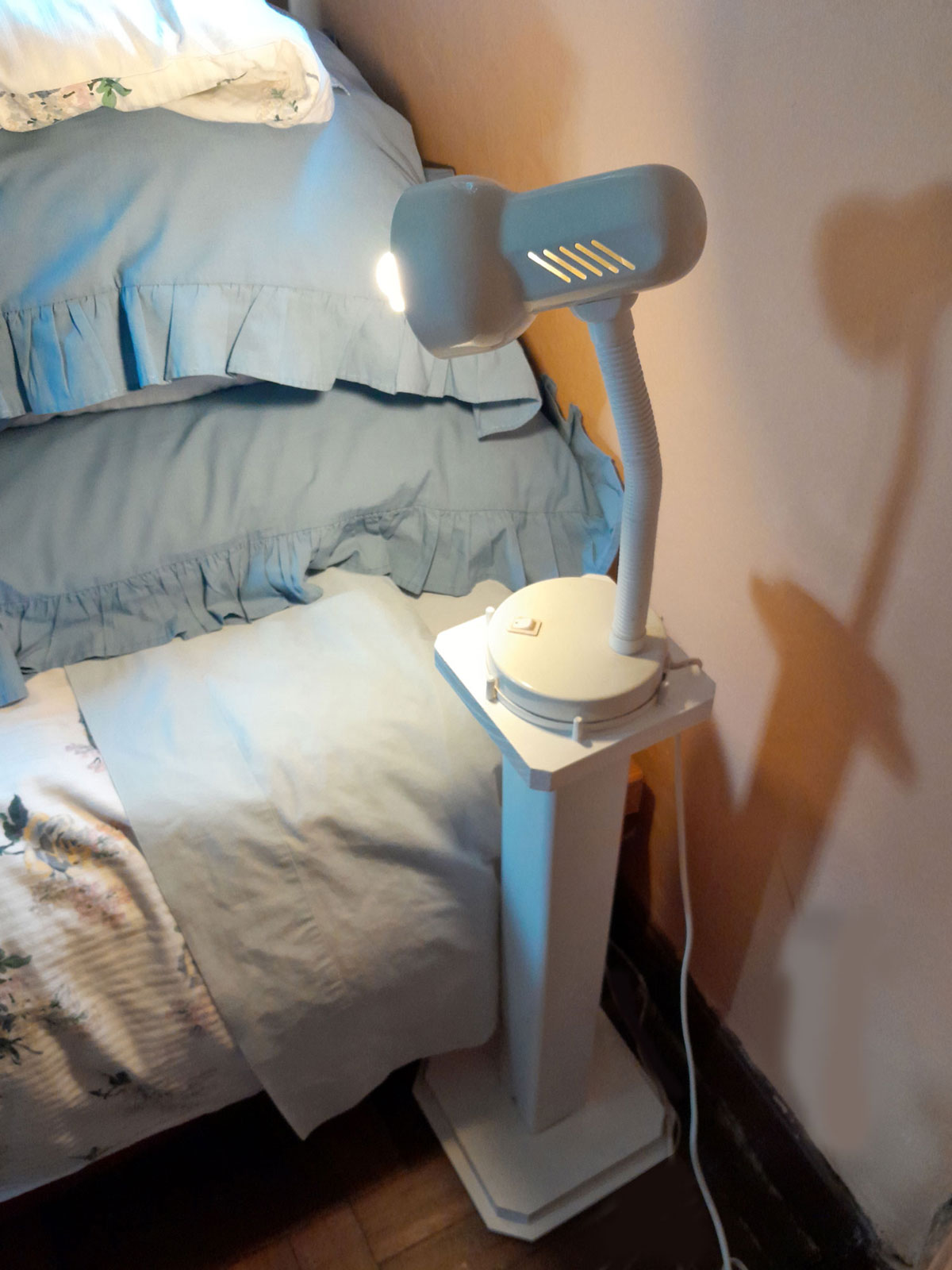
From down-pipe to up-light
Okay, first of all we will admit this is no beauty, but it is very functional, and as it makes use of offcuts from earlier projects, it costs nothing to make.
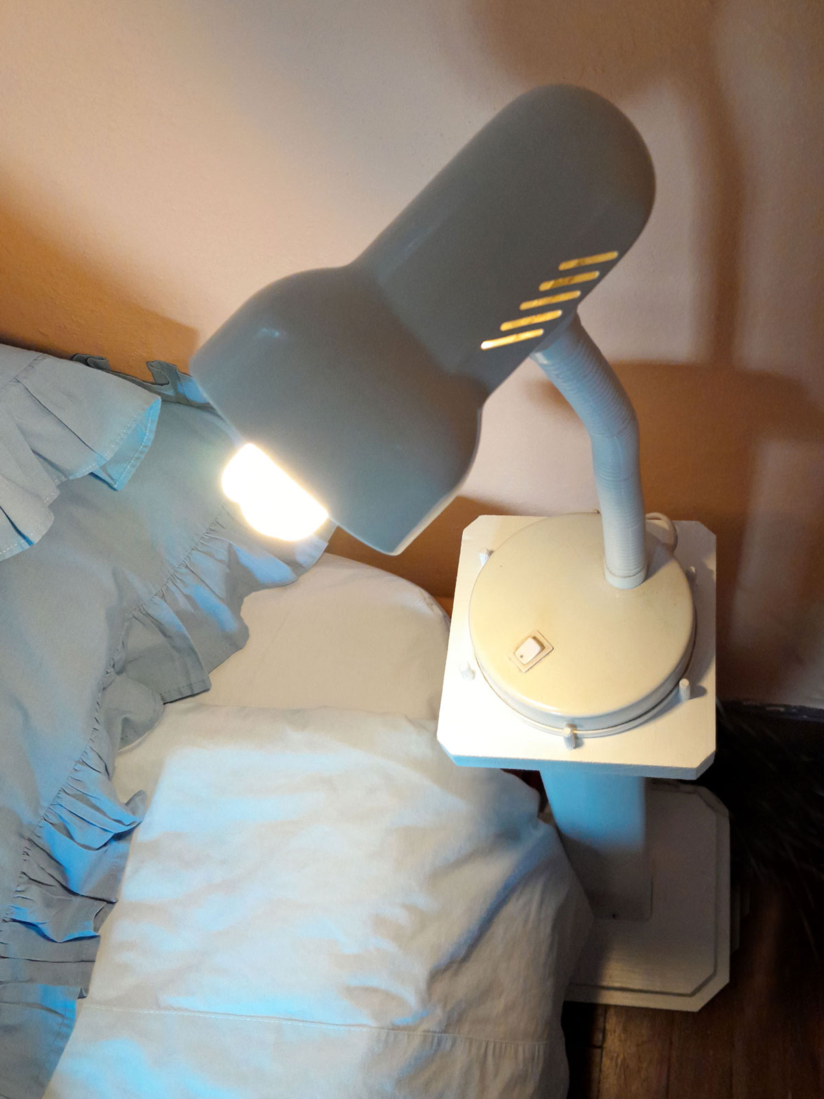
But what it DOES do, however, is put the light right where you want when you want to read in bed.
This unit was made to fit a particular bedside lamp with a circular base with a diameter of 125mm, which is why the top is very compact – roughly 144x144mm (making it as light as possible). This also serves to put the pedestal’s centre of gravity as far down as possible, and the 75mm downpipe is fitted to a base as large as possible, but keeping overall dimensions as compact as possible. (Yes, we know that sounds a bit contradictory, but think about it.) Hence the 8mm MDF base is roughly 280mm on each side, and the upper 22mm SA pine is about 250mm on each side. This gives the base quite a bit of weight, and hence tends to stabilise the unit a lot better.
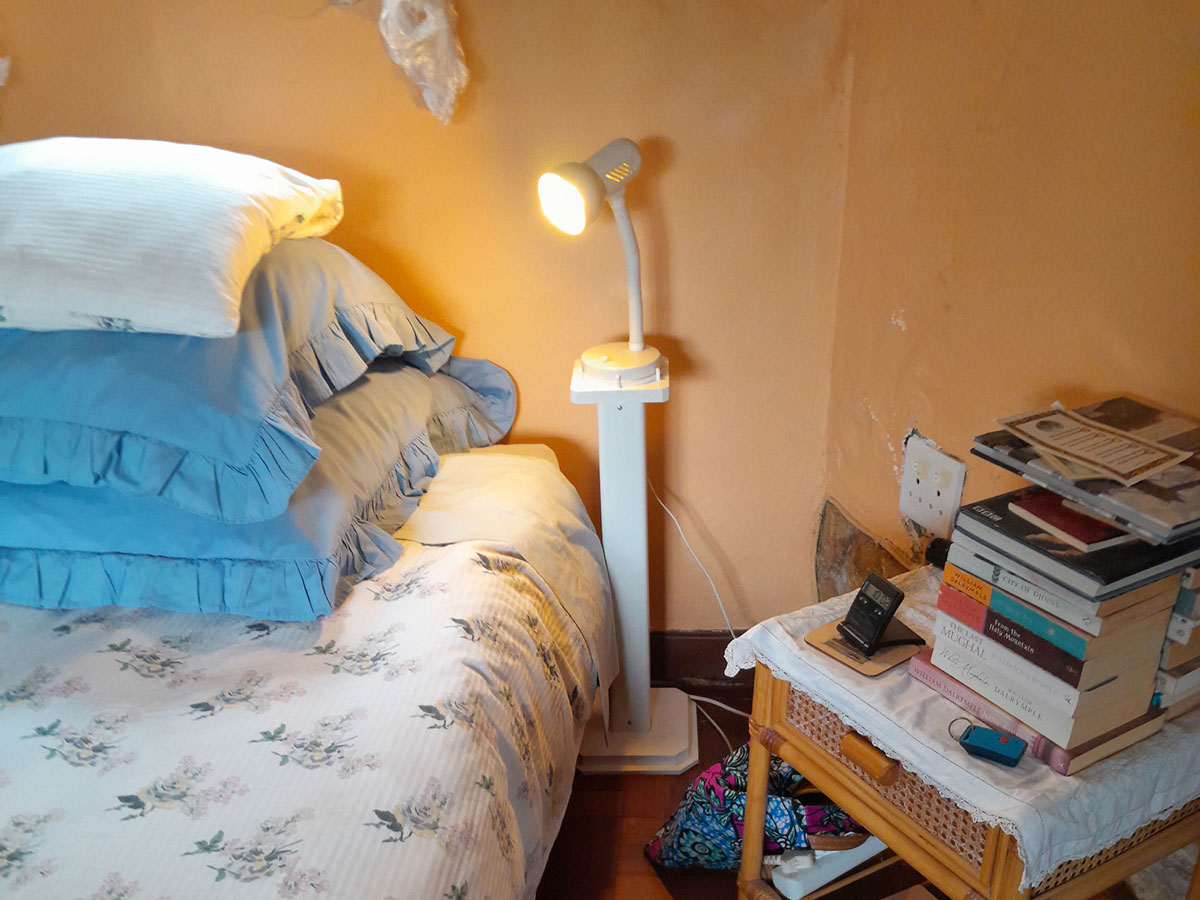
The downpipe offcut is 600mm long and very light, again helping to keep the pedestal’s centre of gravity as low as possible. So, together with the base and top platform, the total height of the unit is just on 650mm. adding the light’s height to that put the lamp itself at around 850mm, providing light right where you want it – on your book’s pages.
One thing you really need to ensure you cut accurately is the column… both ends must be a very precise 90º in both planes, so that the pedestal stands absolutely vertical. If either end is not, problems… if at the bottom, the column will be your very own Leaning Tower of Pisa – and very likely topple; if “off” at the top, the platform for the lamp will not stand level and will irk you, at the very least.
Materials:*
- Top: SA pine, roughly 144x144mm on each edge
- Column: 75mm square profile downpipe offcut, 600mm long
- Base: SA pine, roughly 222x222mm on each side, glued to 8mm MDF offcut, roughly 250x250mm on each side
- Column inserts: SA pine 69x69mm. Bottom one is cut to 70mm long, and to top one to 30mm
- Column locking screws: four 25mm cap screws
- Top and base fixing screws: six 60mm wood screws
- Dowels: six 30x5mmØ
- Wood glue
- Finish: undercoat, on which is applied gloss white spray paint
**Optional column filler: sand, gravel or surplus odd screws, nails or bolts… anything heavy.
*Please bear in mind that as these are all offcuts, the dimensions of the final unit are pretty arbitrary, but they work. Should you want to make use of your own offcuts for something like this, go wild!
**To enhance stability, you could pop some river sand, gravel, or beach sand, or a couple of handfuls of odd bent, rusted or otherwise useless nuts, bolts, screws nails etc, into the column – just enough to fill the bottom 150mm or so – as this will also really enhance stability by moving the centre of gravity even lower towards the base.
Method:
- The basic materials, costing a very easy-on-the-bank-balance of R0.
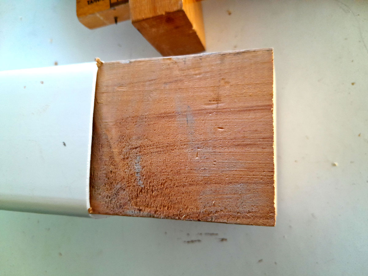
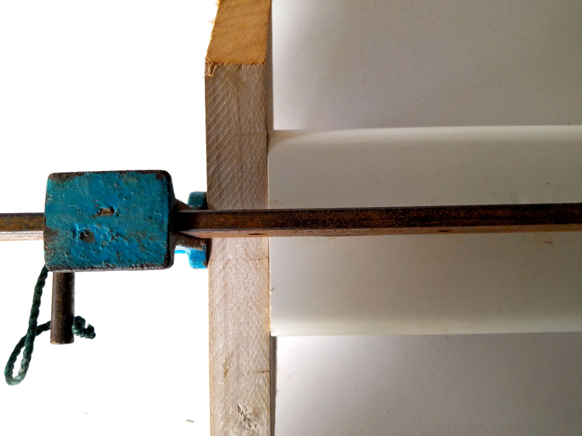
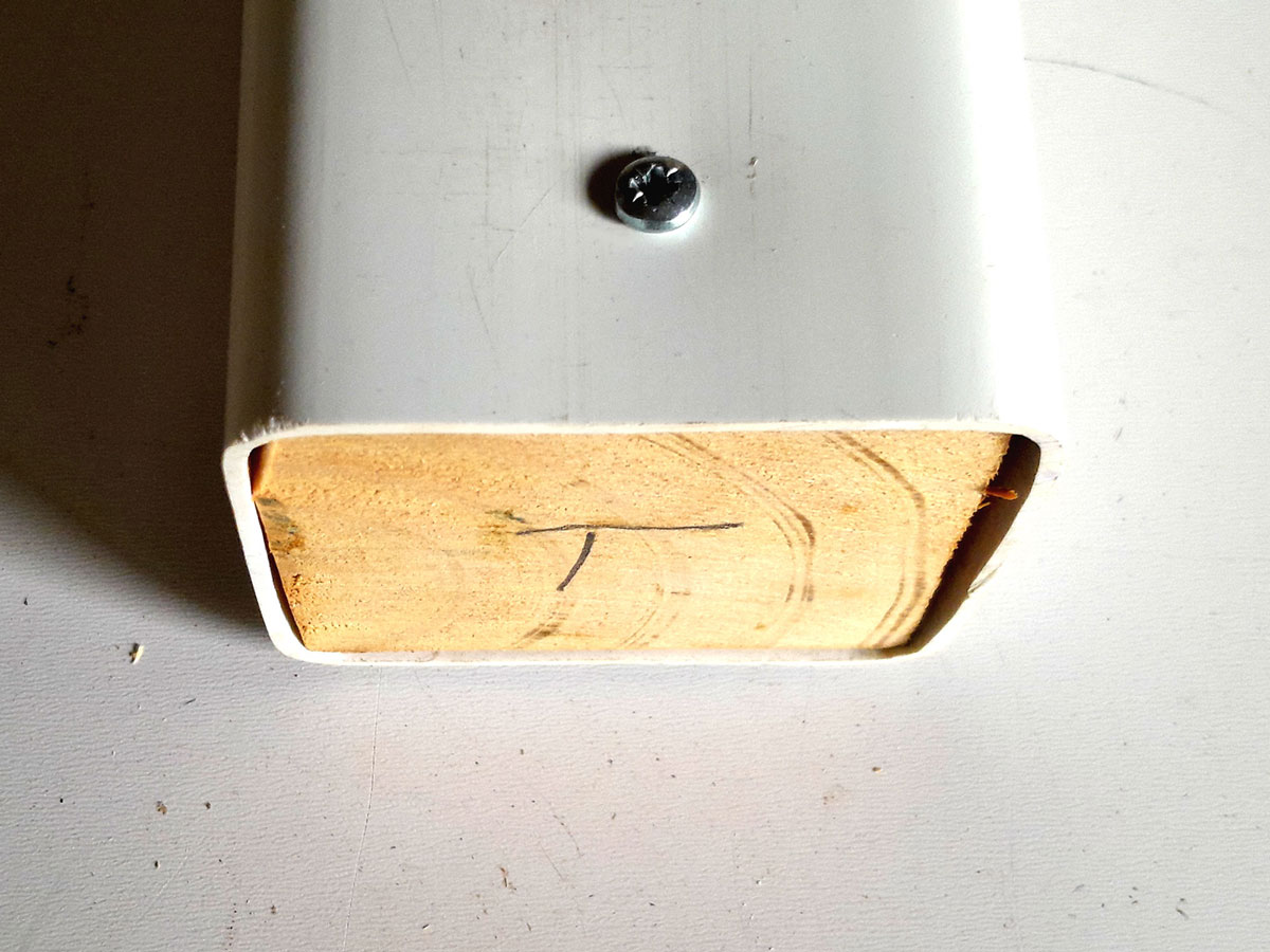
- First of all, I decided to sort out the column and to attach the top and base to it I decided to install 69x69mm inserts into each end. This is the longer (and therefore heavier one) going into the base end.
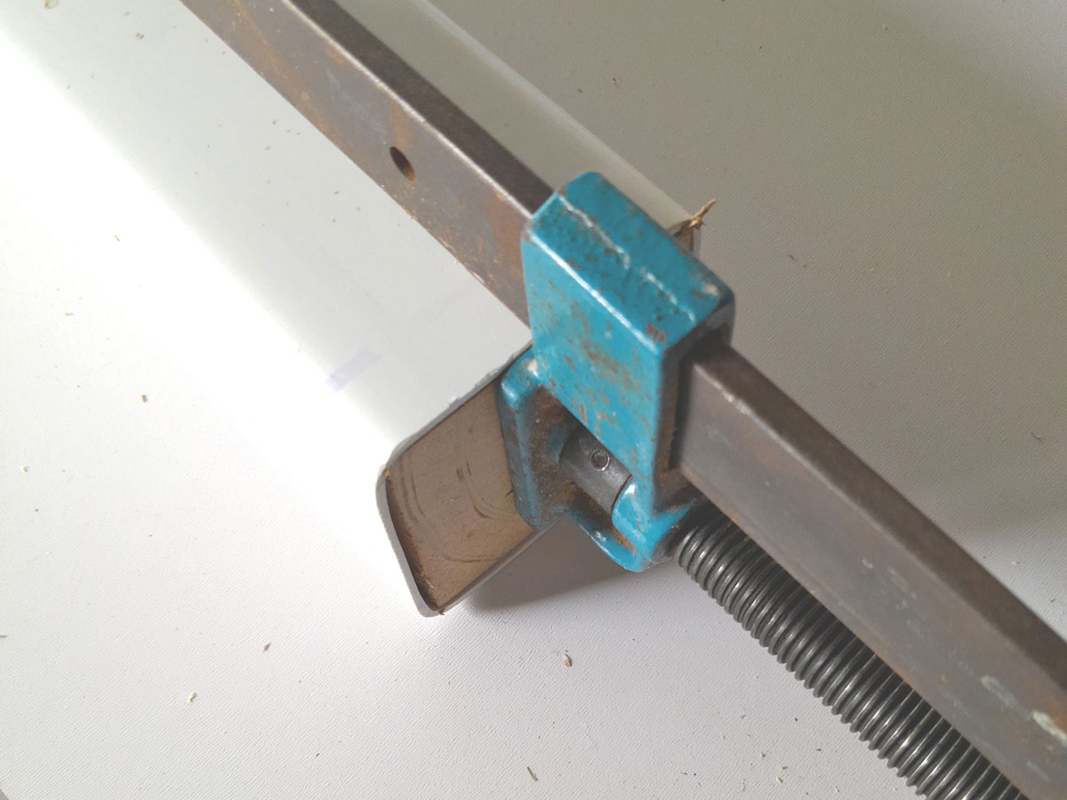
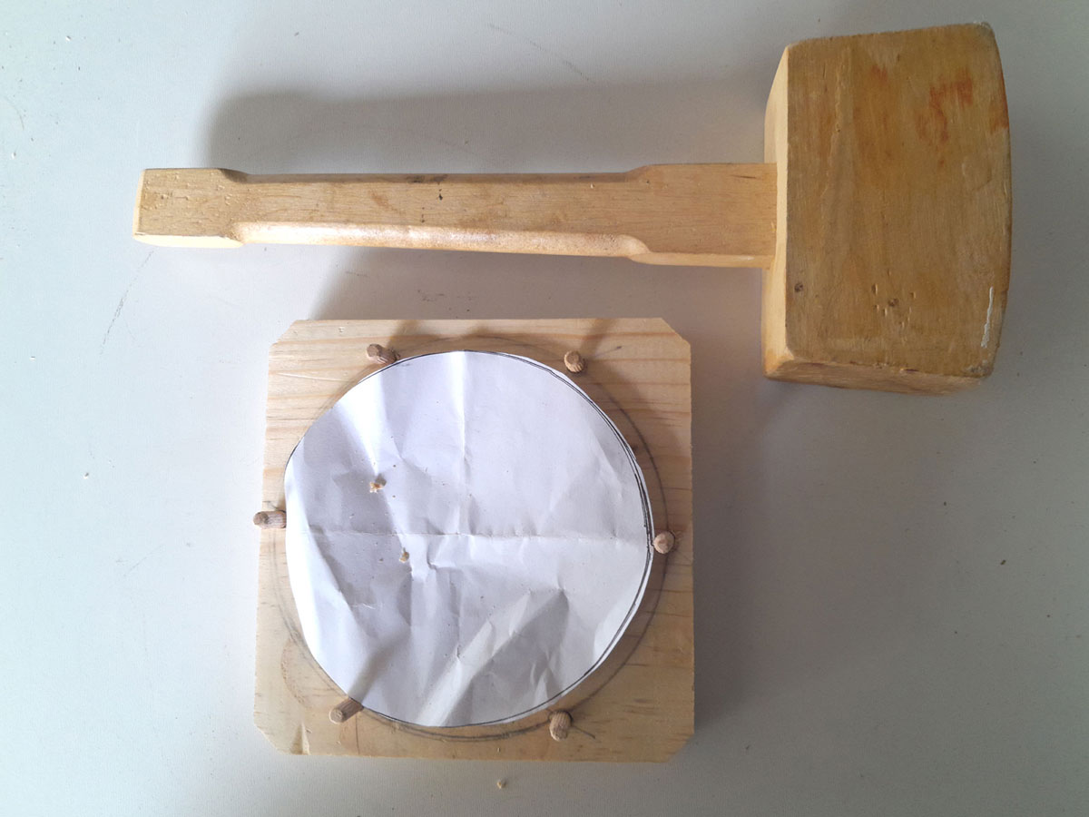
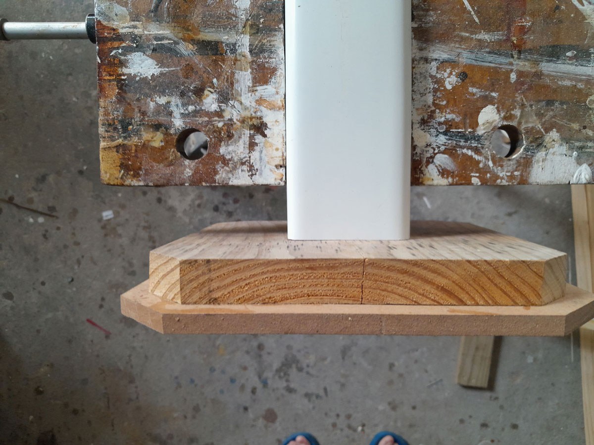
- I used a large 1m bar clamp to push the insert into the base. You could use a wooden mallet to seat the inserts, but you run the risk of splitting the pipe if you are not careful when tapping it into position – so be careful, right?!
- At the top end, I used a piece of offcut as a cushion, and to spread the load.
- Not that it really needs them as the insert is a very tight fit, but I drove in a locking screw on two opposite sides of the column. It is a good idea to mark the inserts appropriately with a “T” and a “B” to you can later easily identify which is which.
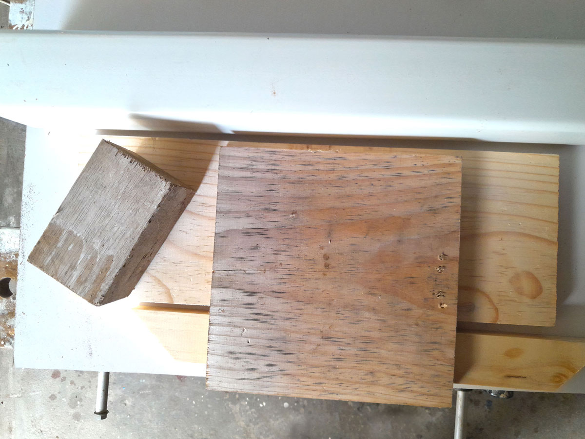
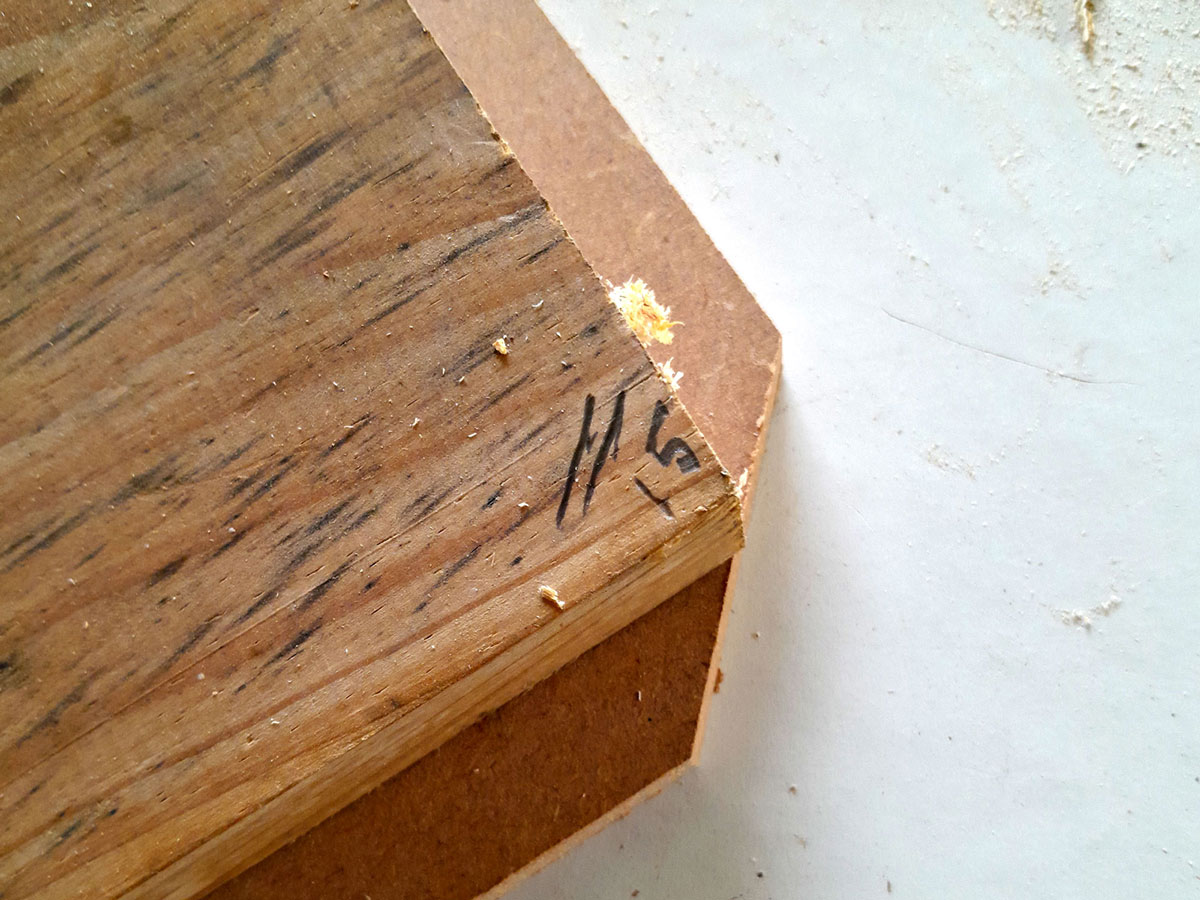
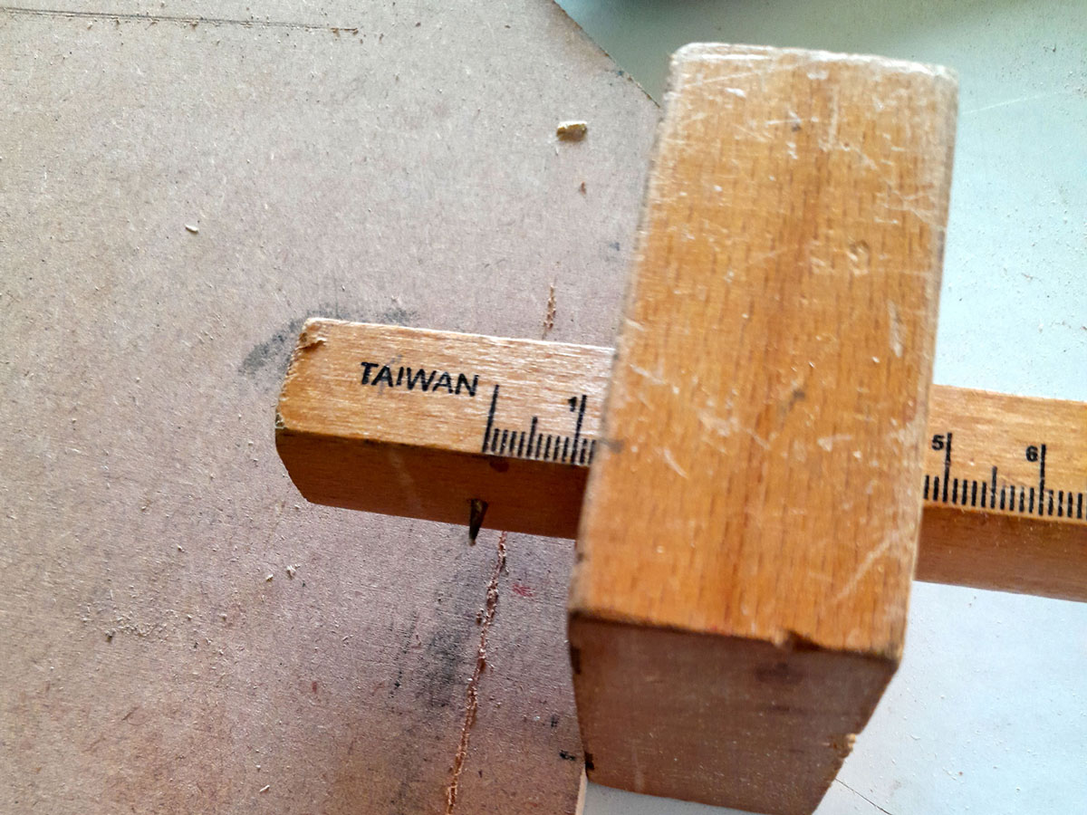
- So that there would not be any sharp 90º corners on which to stub toes or snag delicate material, I bevelled each corner at 45º. Here I marked off the 15mm bevel I would need on the corners of the base upper section.
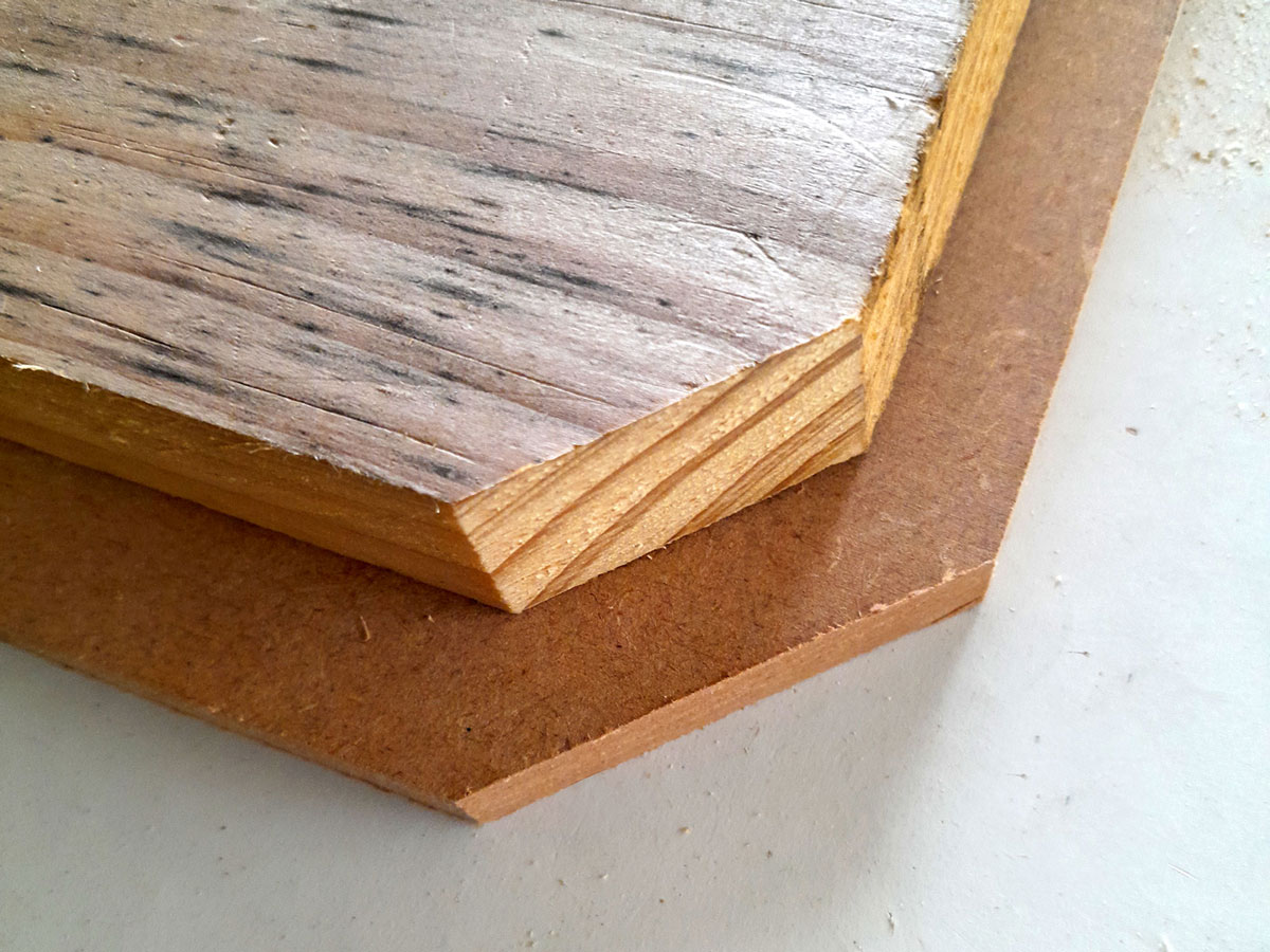
- Here it is in position.
- I used a gauge to lightly mark the alignment lines on the MDF portion of the base.
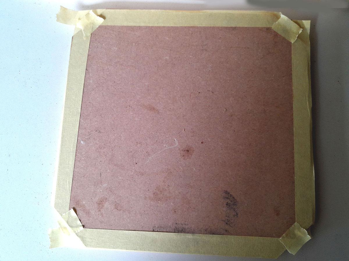
- Then I masked the outer portions off along those lines so that any glue oozing out of the join would not mar the surface.
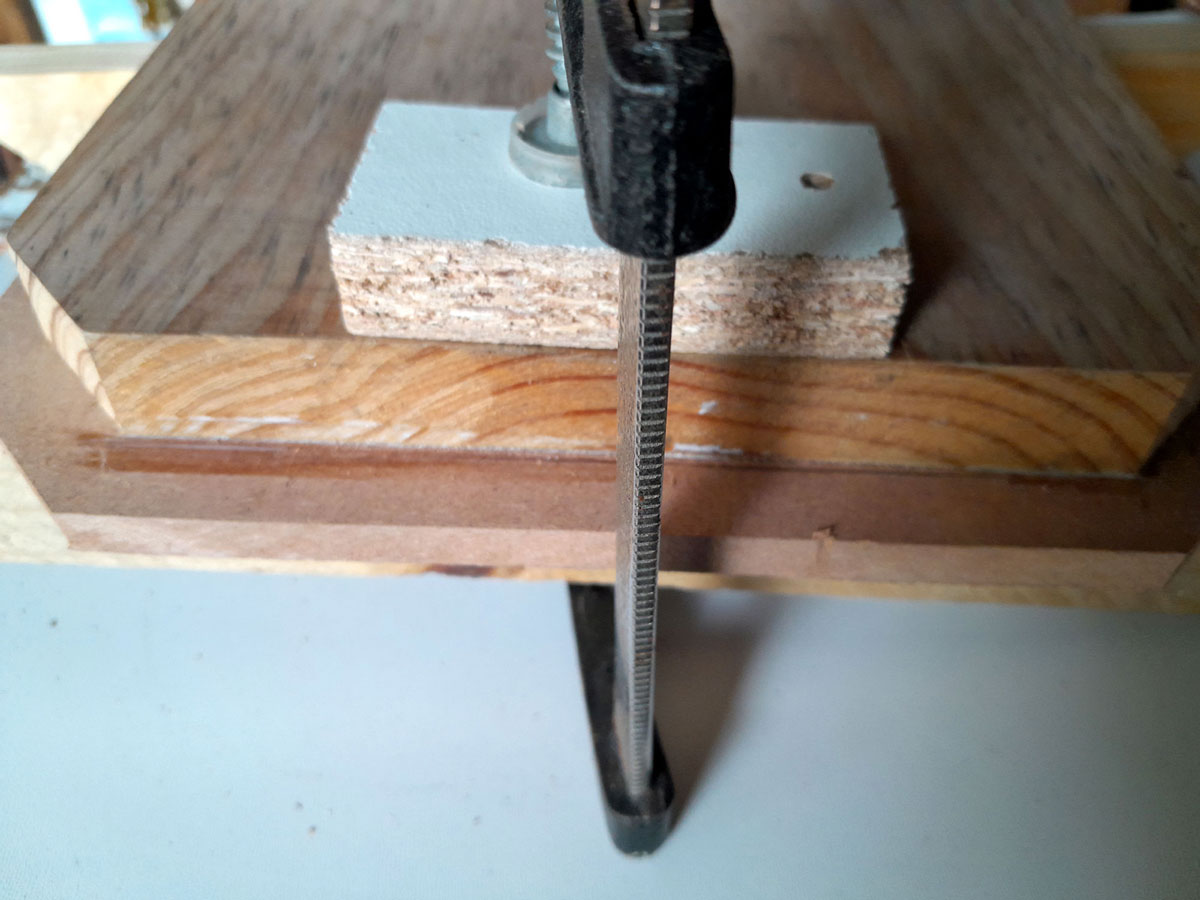
- Then I applied glue and clamped the top and bottom section of the base together, and removed the tape after any glue has oozed out. Note the use of the cushioning blocks to avoid marring the wood’s surface, but also to spread the clamping pressure over a wider area. The clamps I used here are small 150mm bar clamps.
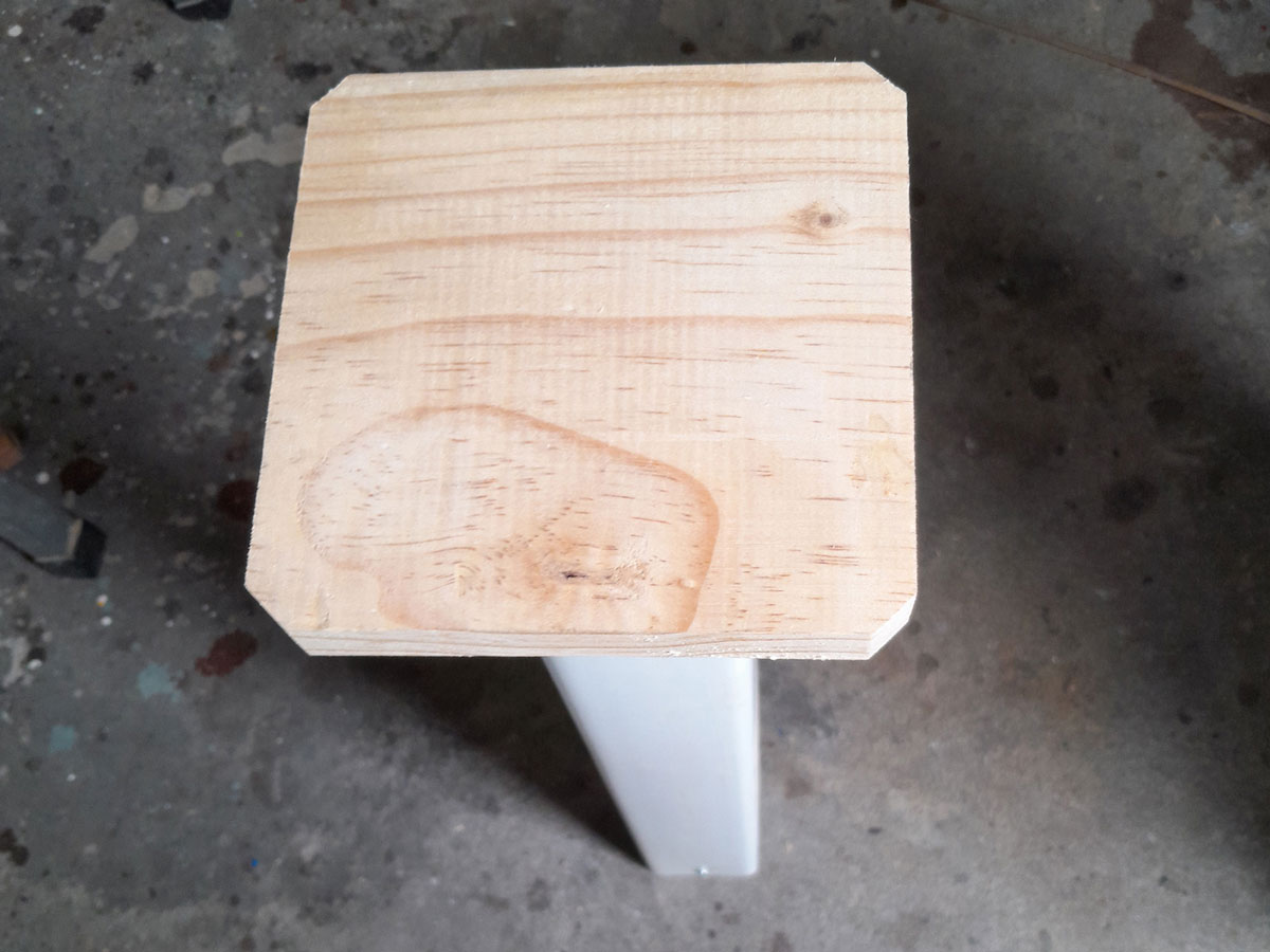
- I cut the top from an offcut of 142x142mm SA pine. Here it is resting on the top of the column… and the fact that the latter is standing perfectly vertical is proof that the cuts were accurate.
- Note that the top of the column (with the shallower insert) is marked with a “T”.
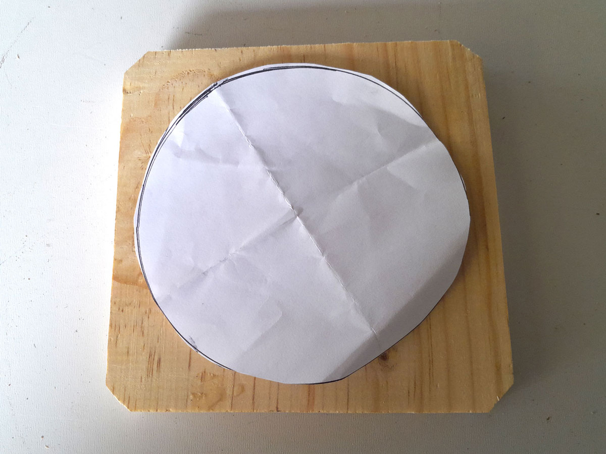
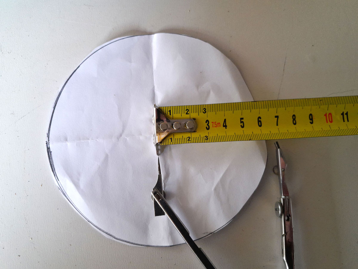
- Now for the light’s platform… I had drawn the outline of the actual lamp base on a piece of A4 paper and cut it out.
- As you can see, the circle is just on 130mmØ… that is because the pen’s line, obviously, is on the outside of the actual edge of the base.
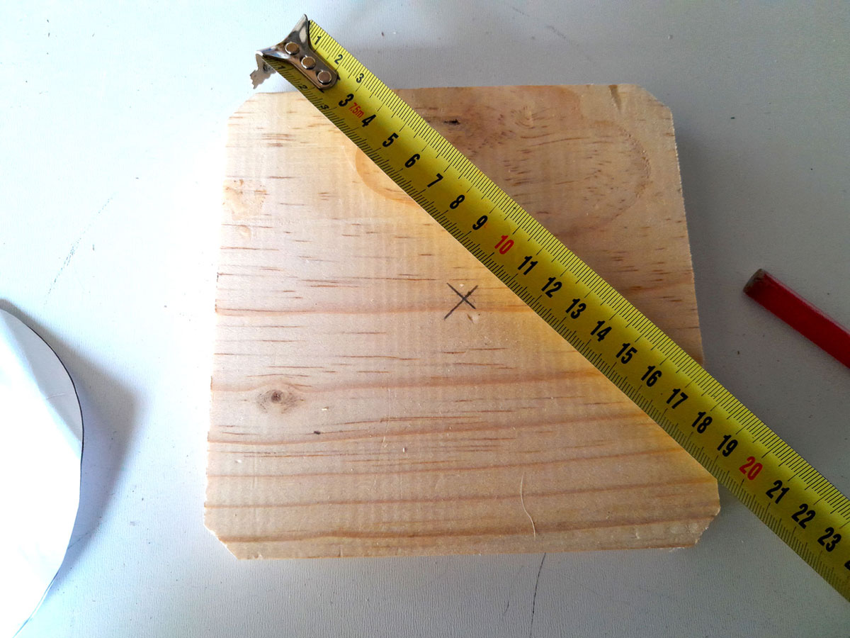
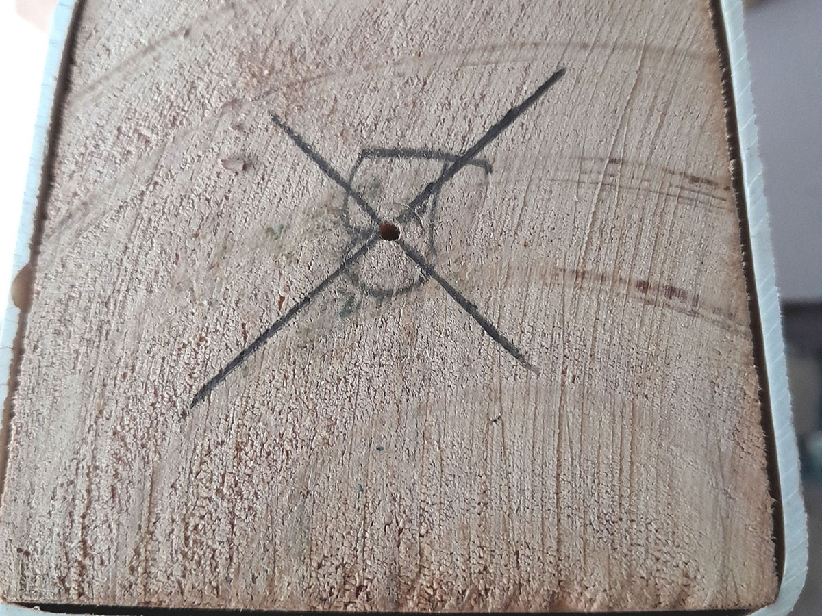
- I marked off the centre point of the lamp’s platform.
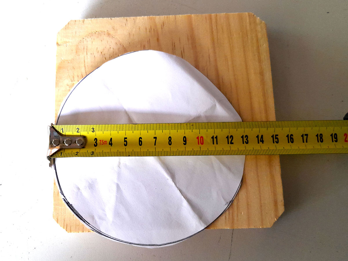
- I measured the lamp base’s radius again, to confirm it… remember, always check your measuring twice or more before cutting or drilling.
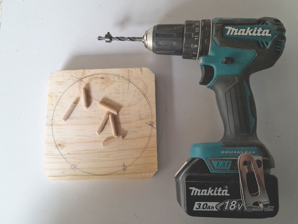
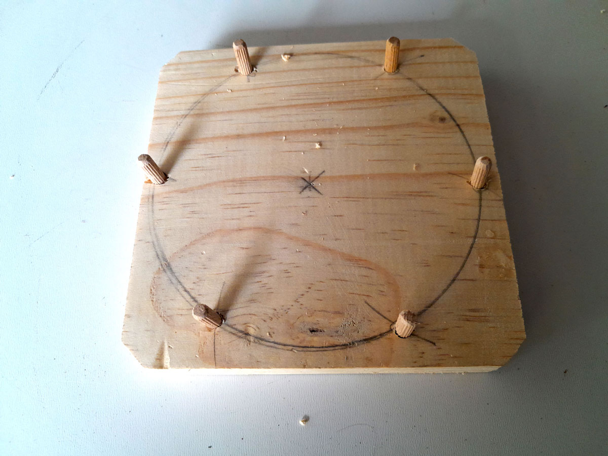
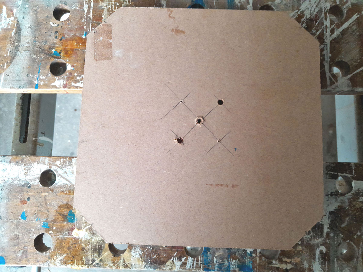
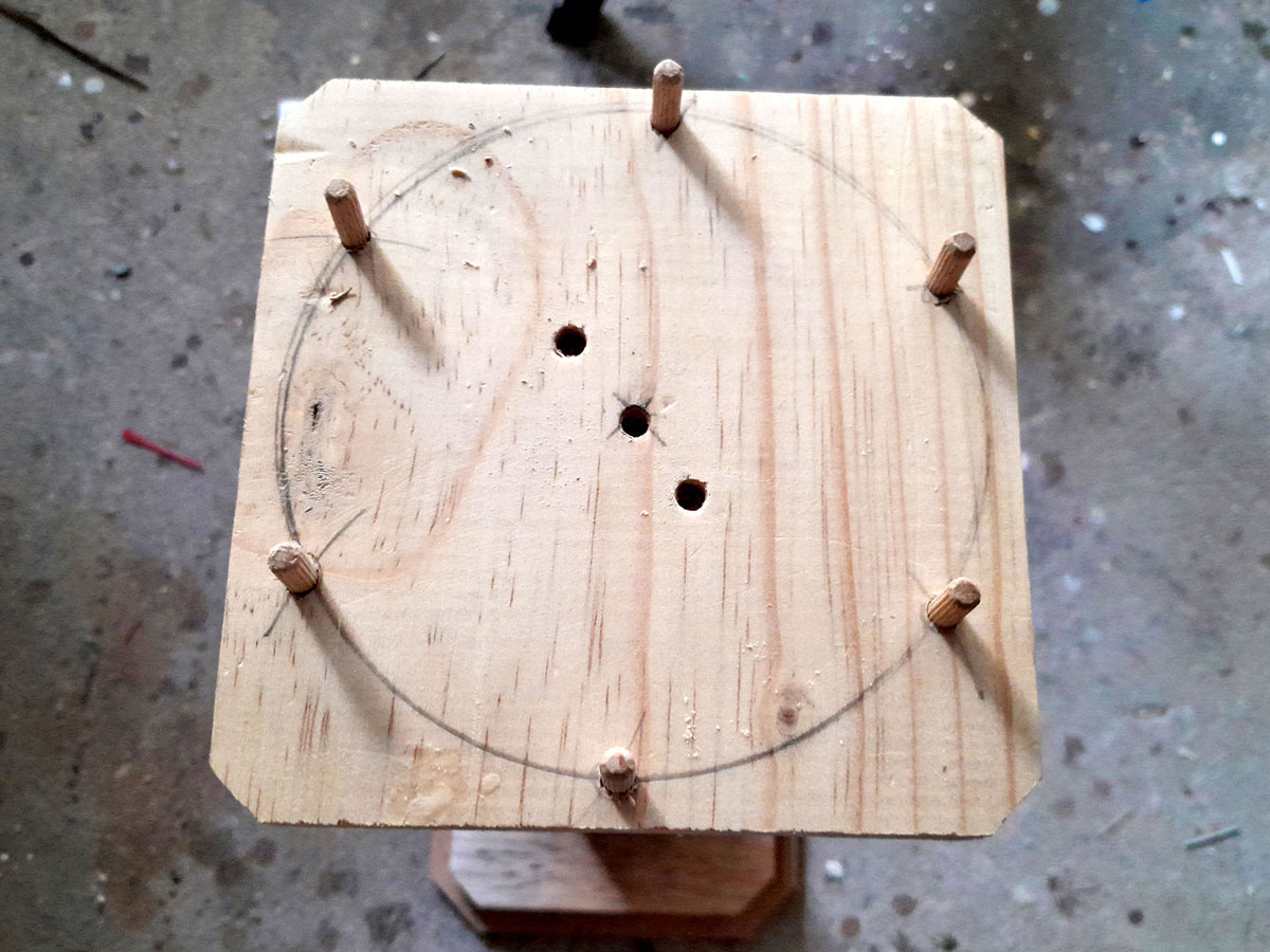
- Then I used a compass to inscribe the circle for the lamp base, and the compass again to mark the positions of the six 30x5mmØ dowels at equal 60º intervals.
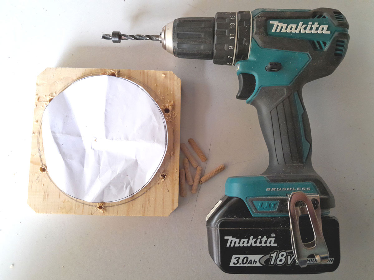
- Then I drilled the dowel holes to a depth of 15mm.
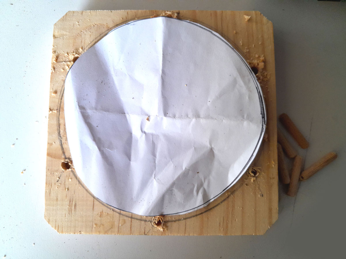
- And confirmed 100% that the dowel holes were slightly outside of the lamp’s base radius, so the latter would be able to nestle comfortably within the circle of dowels.
- Then I used a mallet to tap the dowels into their holes. Note that the dowels are not glued into place, but can be removed if the pedestal ends up having a change in use, and the dowels would get in the way.
- But here they are and the reason for them is to keep the lamp in position on the pedestal, should it be knocked at all.
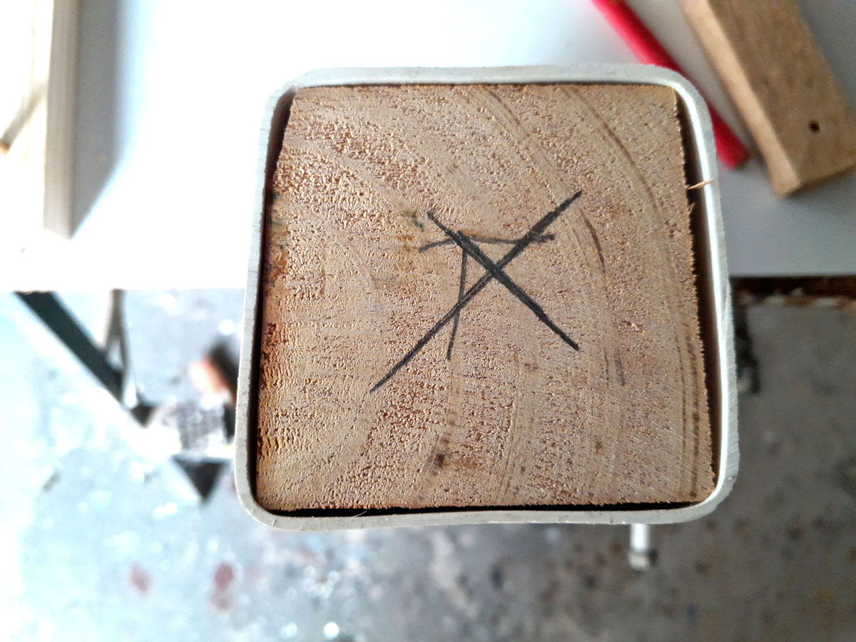
- Then I marked off the centre of the top.
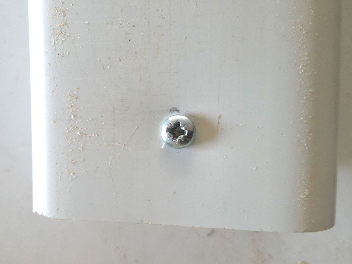
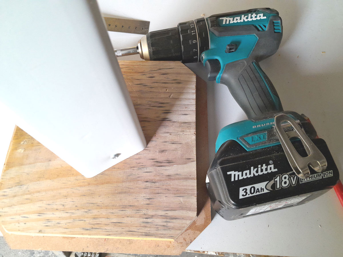
- Then I drove a 60mm screw through the pedestal top platform so that it protruded, as shown here. I repeated exactly the same process on the base.
- Then I drilled a small 2mmØ pilot hole at the centre point of the base insert. (Note the “B”)
- Putting the tip of the screw into the pilot hole, I drove it fully home, countersinking it into the MDF of the base. At you can see, the base is not sitting square. NO PROBLEM…
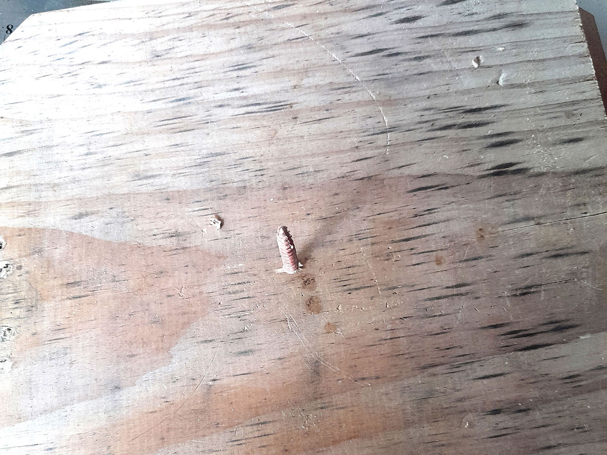
- The single screw acts as an axle so you can rotate the column to the desired position.
- Then I drove in two more securing screws as shown (taking great care to ensure that they were both within the area of the insert. This locks the column in position very firmly. However, as a bonus, if one wants to change the size of the base or top, for that matter, both can be easily removed from the column. Crafty, eh?!
- I repeated the process on the top (I did it after securing the base because I had already driven in the dowels), again driving the screws in deeply enough to countersink them. I finished off with a light sanding, masked off the downpipe column, and applied an undercoat to the top and base, then did a second light sanding to smooth the surfaces, and finished off with two coats of a high-gloss white spray.
- And here we are… as you can see the dowels hold the lamp base neatly in position, but without locking it down… there is a little play.
CHOICE OF FINAL PIX - Let there be light – and there was… and at last it was at a height at which it actually did what it is supposed to do.
Tools:
Circular cut-off saw, or better still a mitre saw; drill/driver, drill bit of the required size for the dowels, plus a depth-stop; bar clamps; sandpaper.
Project guide
- Difficulty: Beginner/Novice
- Estimated time: 4-5 hours
- Cost: R0
These materials are available at Selected Mica Stores. To find your closest Mica and whether or not they stock the items required, please go to www.mica.co.za, find your store and call them. If your local Mica does not stock exactly what you need they will be able to order it for you or suggest an alternative product or a reputable source.