08 January 2026

How’s this for a grand stand?
This pot plant stand has been designed to suit a particular tray/pot size, but can be resized to whatever diameter tray and pot you like. Just beware of making it too high and too narrow, as this would be more unstable than a slightly squatter version such as the one featured here… which is very stable.
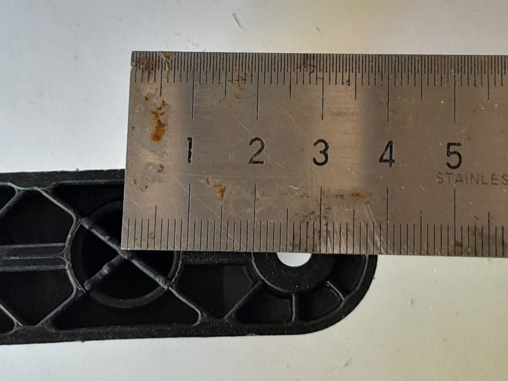
In this particular case, the tray is just over 345mm in diameter, so the stand’s arms were spaced 360mm, to allow for a neat fit, but allowing for a little clearance… namely, about 7mm or so one each side.
Naturally, if you decide to make one of these for your own pot plants, you can adapt this stand’s dimensions as you see fit… diameter, height, lower rest height from the ground, and so on.
In this case, arm spacing is 360mm, so total outer width of the arms is 410mm, total height is 653mm, comprising top and bottom caps, top arm of 65mm, upright of 450mm, feet of 75mm, and two T-connectors, each 25mm.
The lower cross bar assembly is ideal for a second pot plant, if you wish… perhaps a more erect one rather than a trailing one such as a creeper, which could be stepped on. The thing is that contrasting foliage can in its own right be most attractive.
Materials:
- Aluminium – 25mm square section: Two lengths of 2.5m, cut to:
- Four tops – 65mm
- Four legs – 450mm
- Four feet – 75mm*
- Two cross arms – 360mm
- Four short cross arms – 158mm
- Polymer 25mm square connectors:
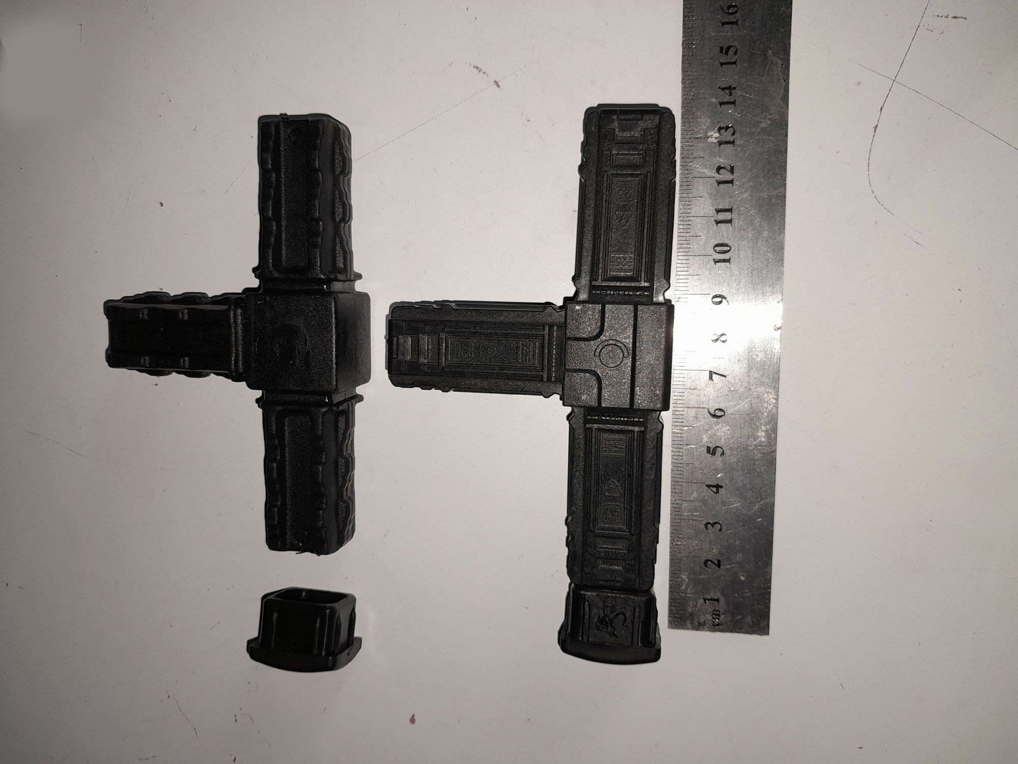
- Eight T-connectors
- Four braces (cruciform 25mm X connectors were not available
- Eight male end caps
- Stainless steel pan head Pozidriv self-tapping screws – 5mm x 16mm (size 12×16)
*I actually could have made the feet longer, say 100mm or so, but didn’t.
Method:
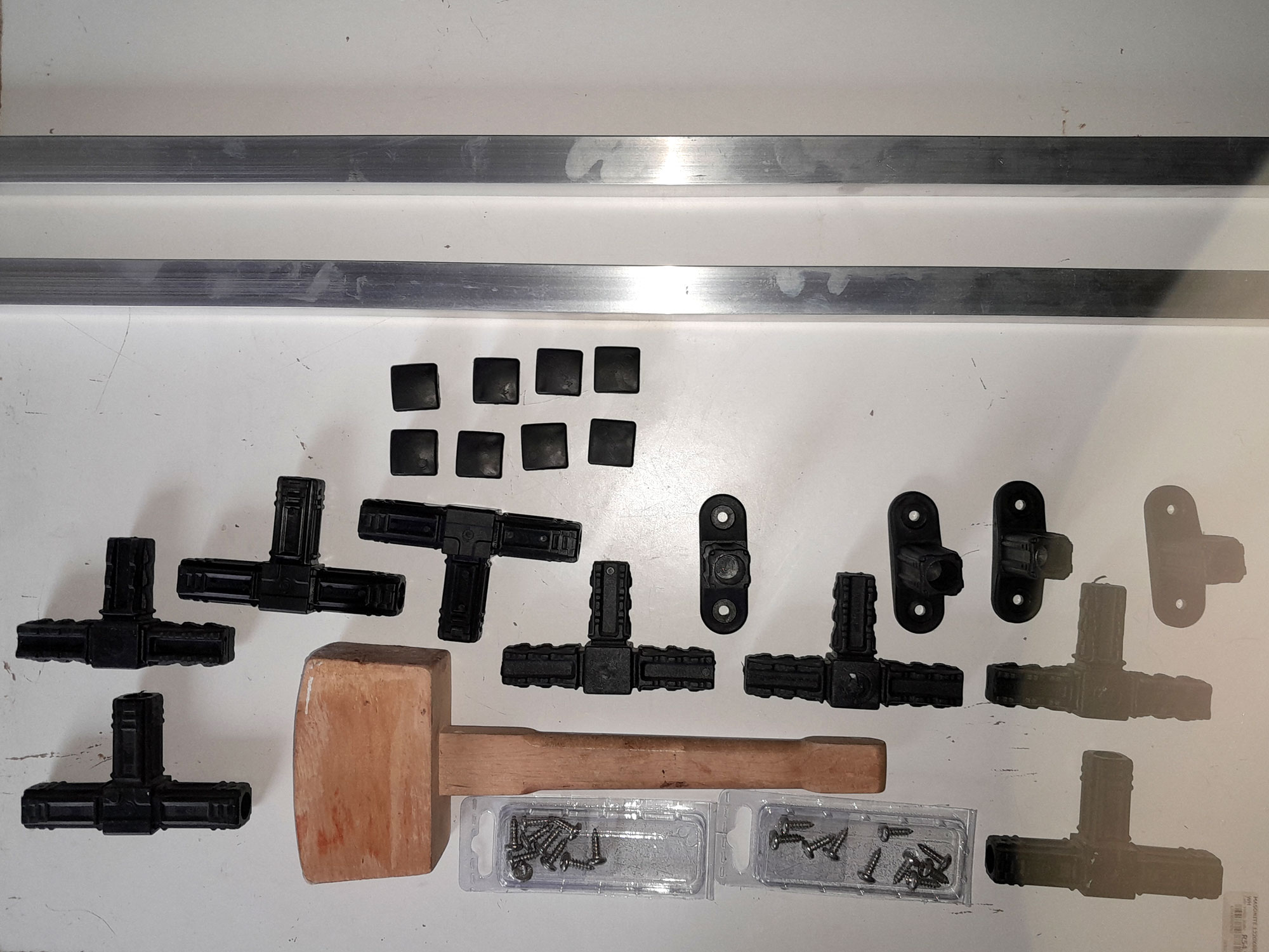
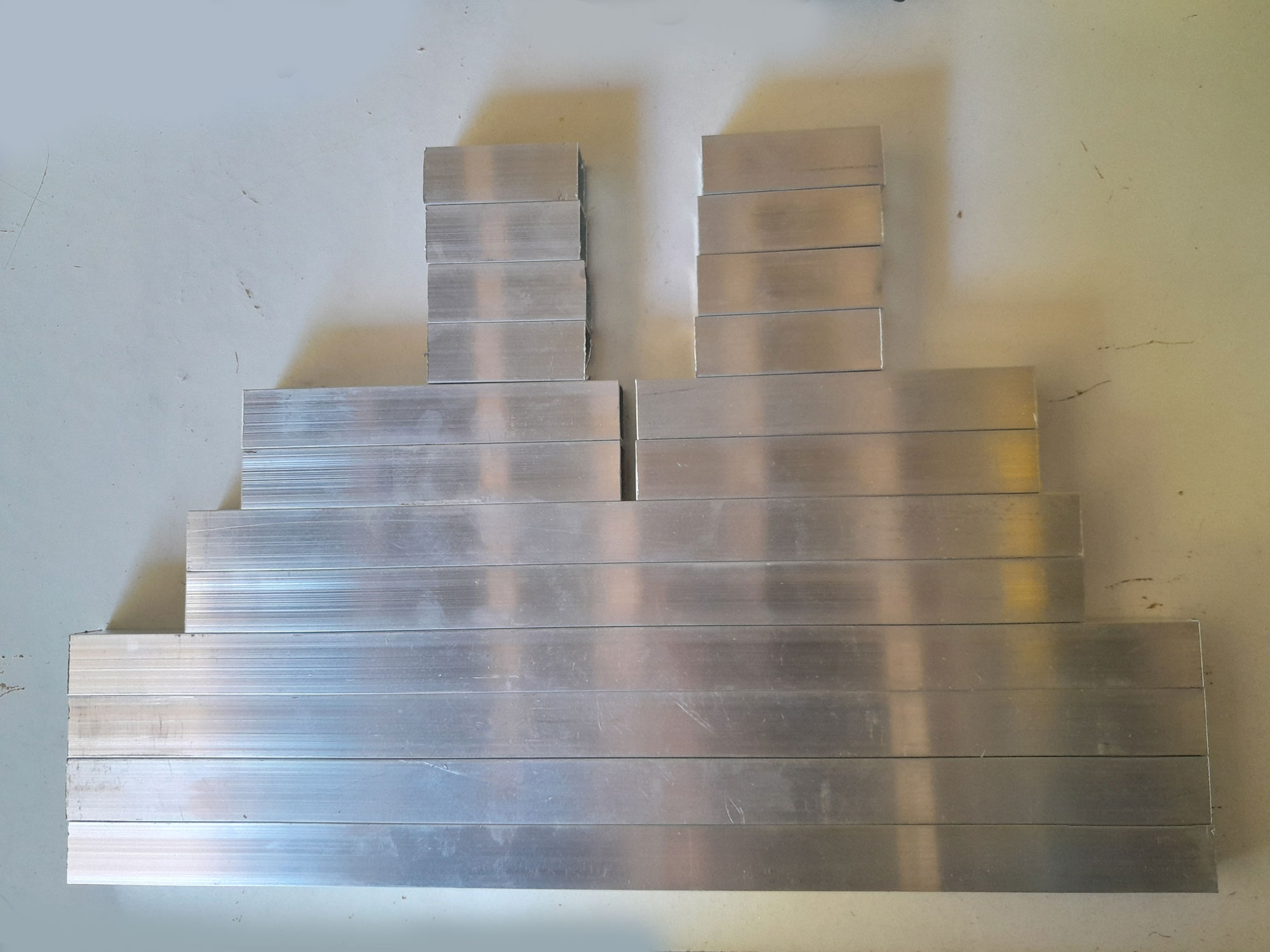
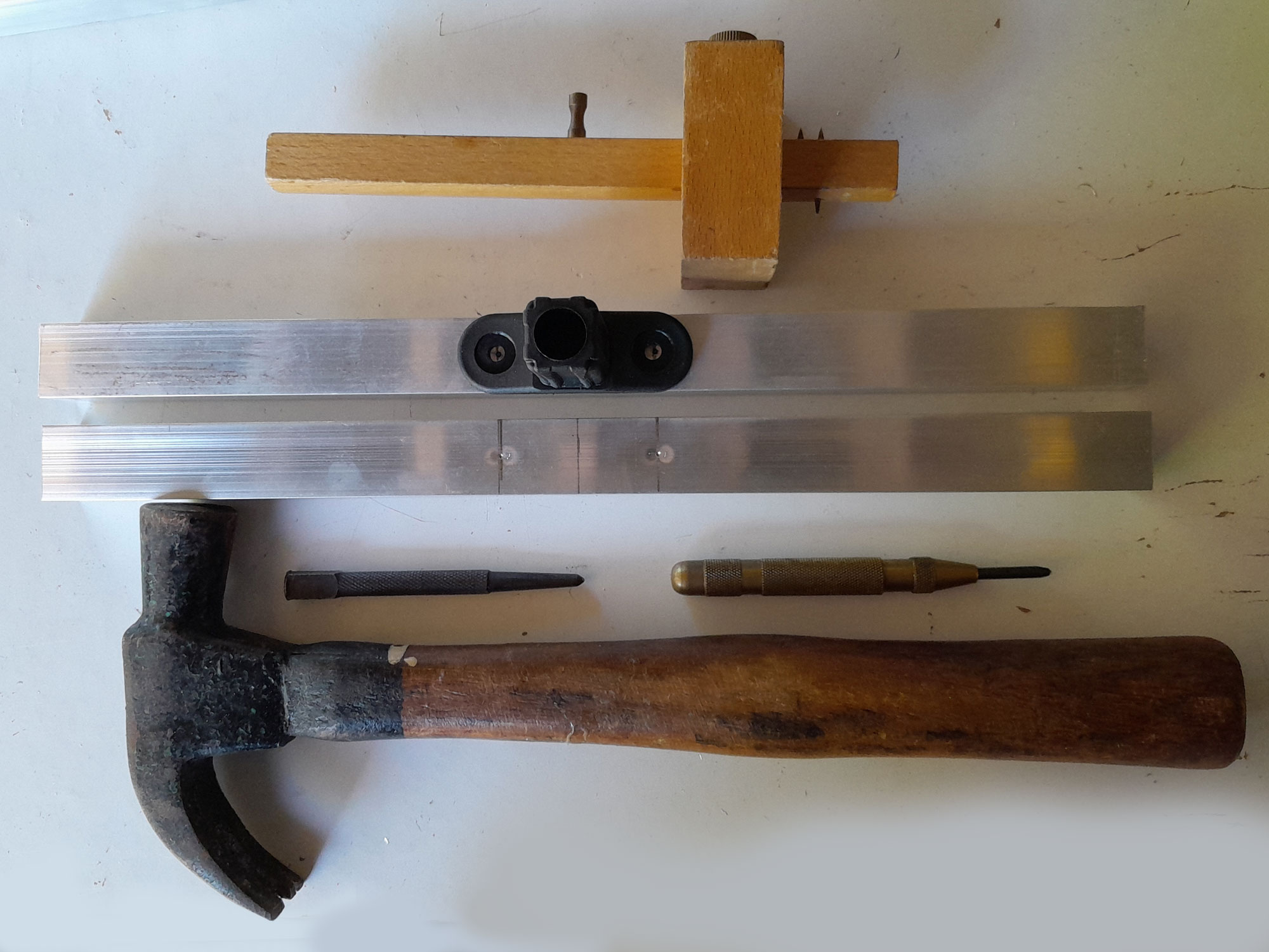
- Here are the components. There are quite a few of them, but once all the cutting is done, and braces attached, assembly is quite quick.
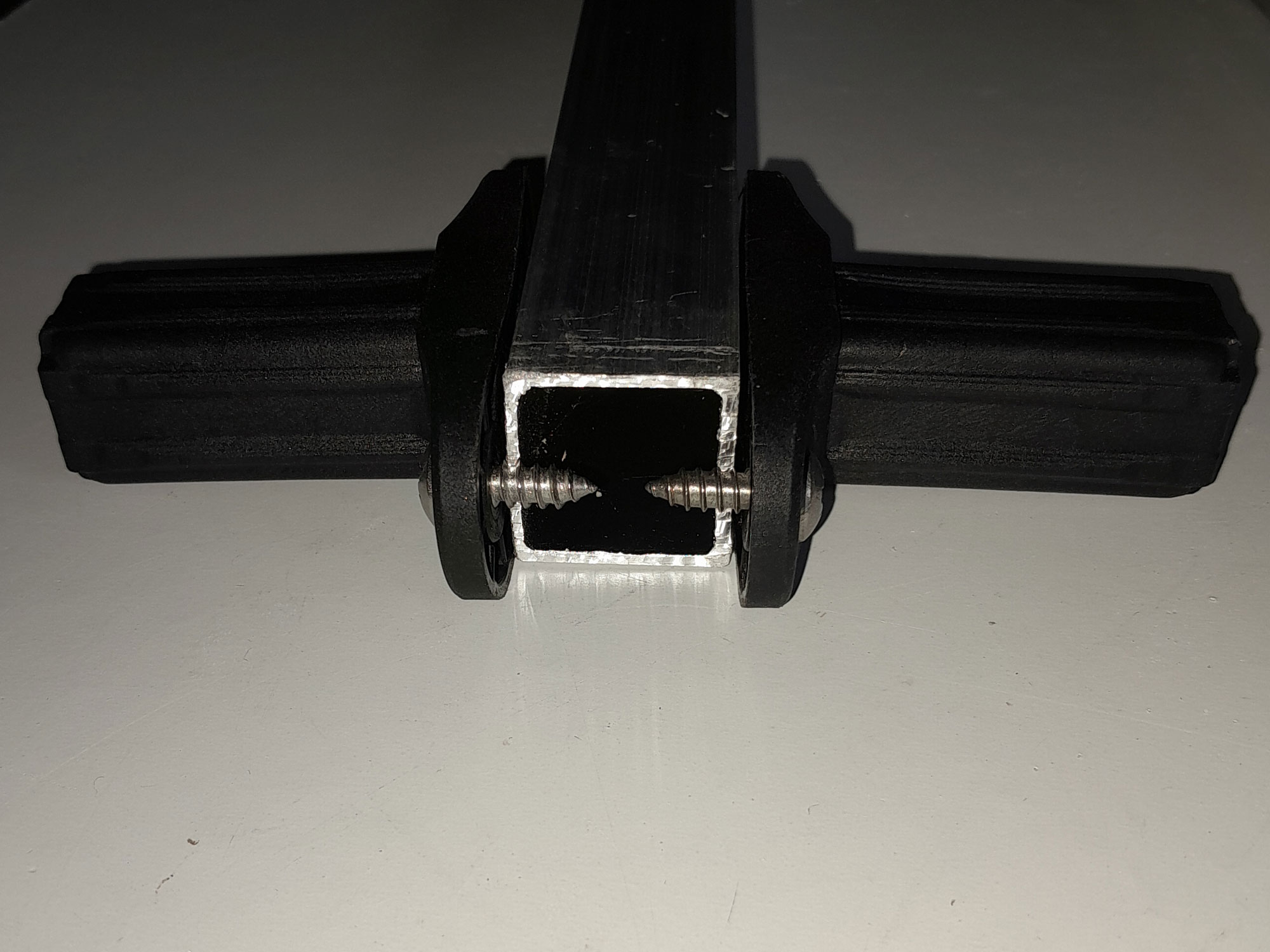
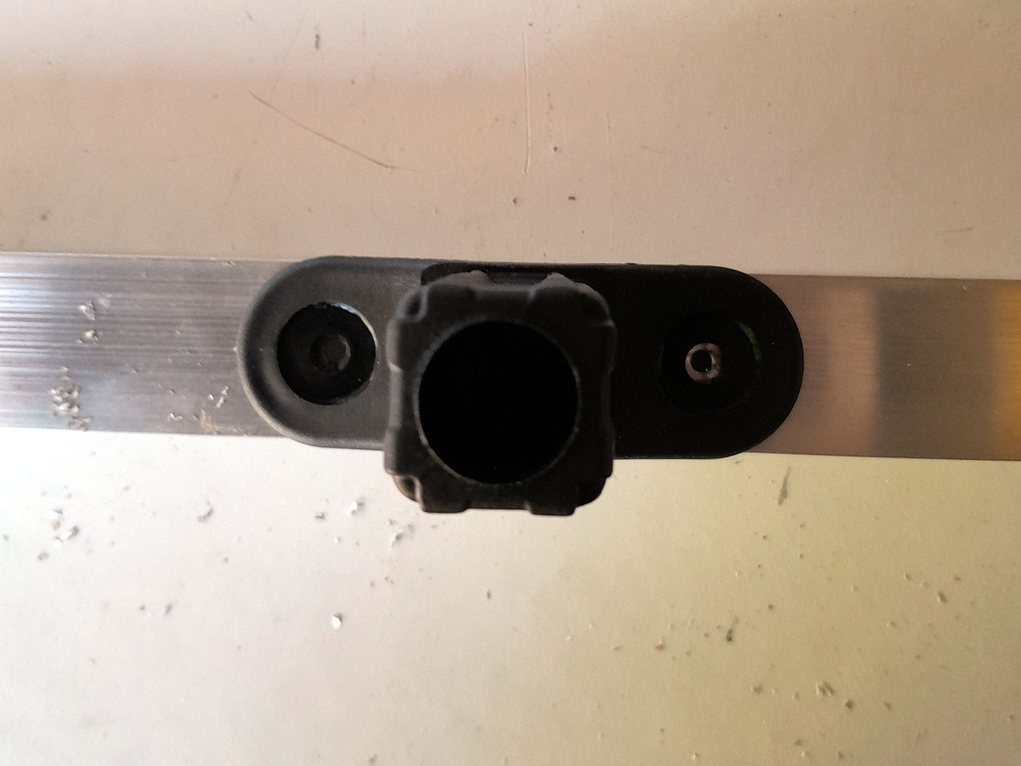
- First of all, I checked that the 12×16 securing screws would fit – i.e., not meet – when used to secure the braces; naturally, the braces would have to align perfectly for the stand to accept a round tray. As you can see, the screws will not meet. If you find that you use a different screw size and/or different square-section aluminium, and the screws you are using do just meet, the solution, when securing the braces, is to follow the same procedure as detailed below, drive one screw in through each pilot hole to establish a thread. Then remove it, and nip off the tip, so you can still insert the screw into the pilot hole, but the tips do not meet in the middle.
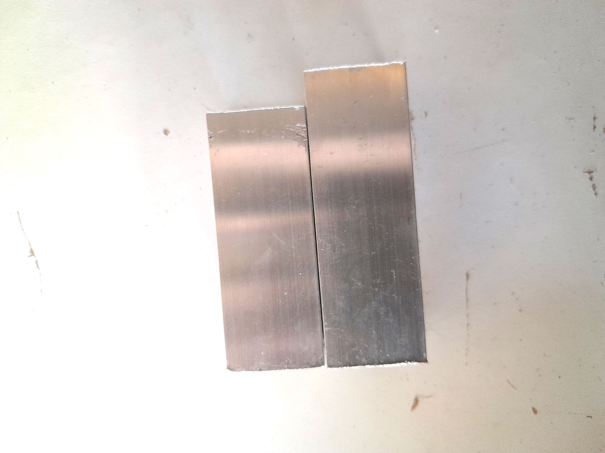
- The four tops would be just long enough to be seated firmly on the T-connector, and accept the end cap. I placed them together, as shown, and measured off the clearance – i.e. the length of each top. I added a couple of millimetres to ensure no hassles later on, to establish how long each top would need to be.
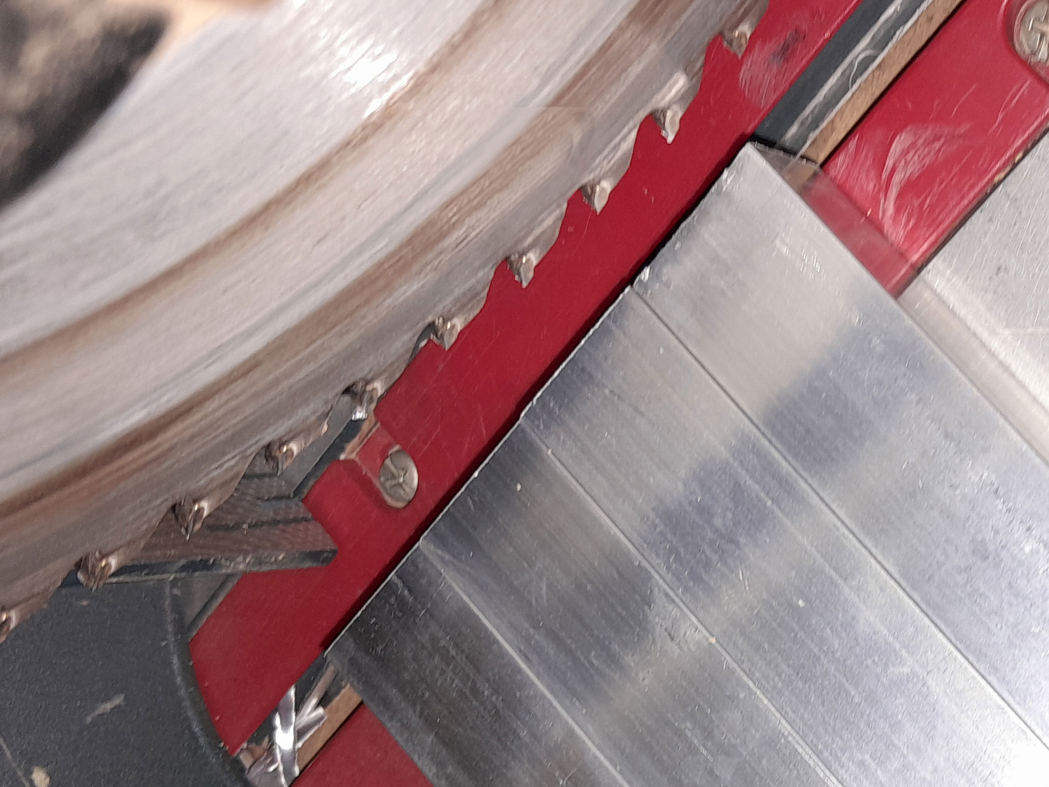
- Then I measured off and cut the first 360mm cross arm.
- As with all the cut ends, I filled down the ends where the saw had left a slightly sharp edge.
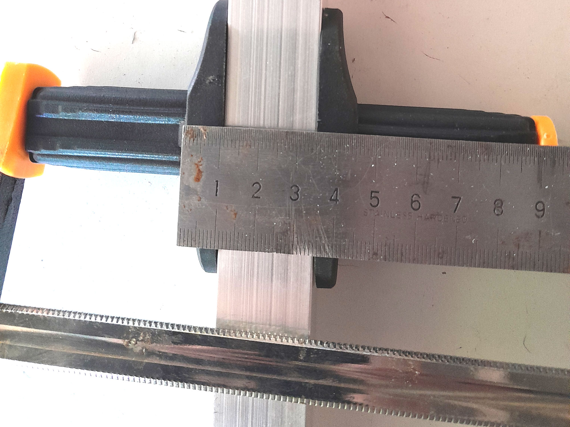
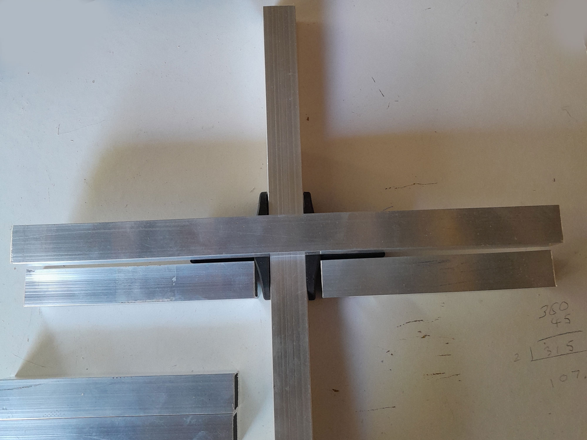
- Having cut both cross pieces, I positioned the braces dead centre, and took the opportunity to measure the total width of the braces and cross arm when fitted together. This would give me the length required for each of the four short cross arms – 158mm.
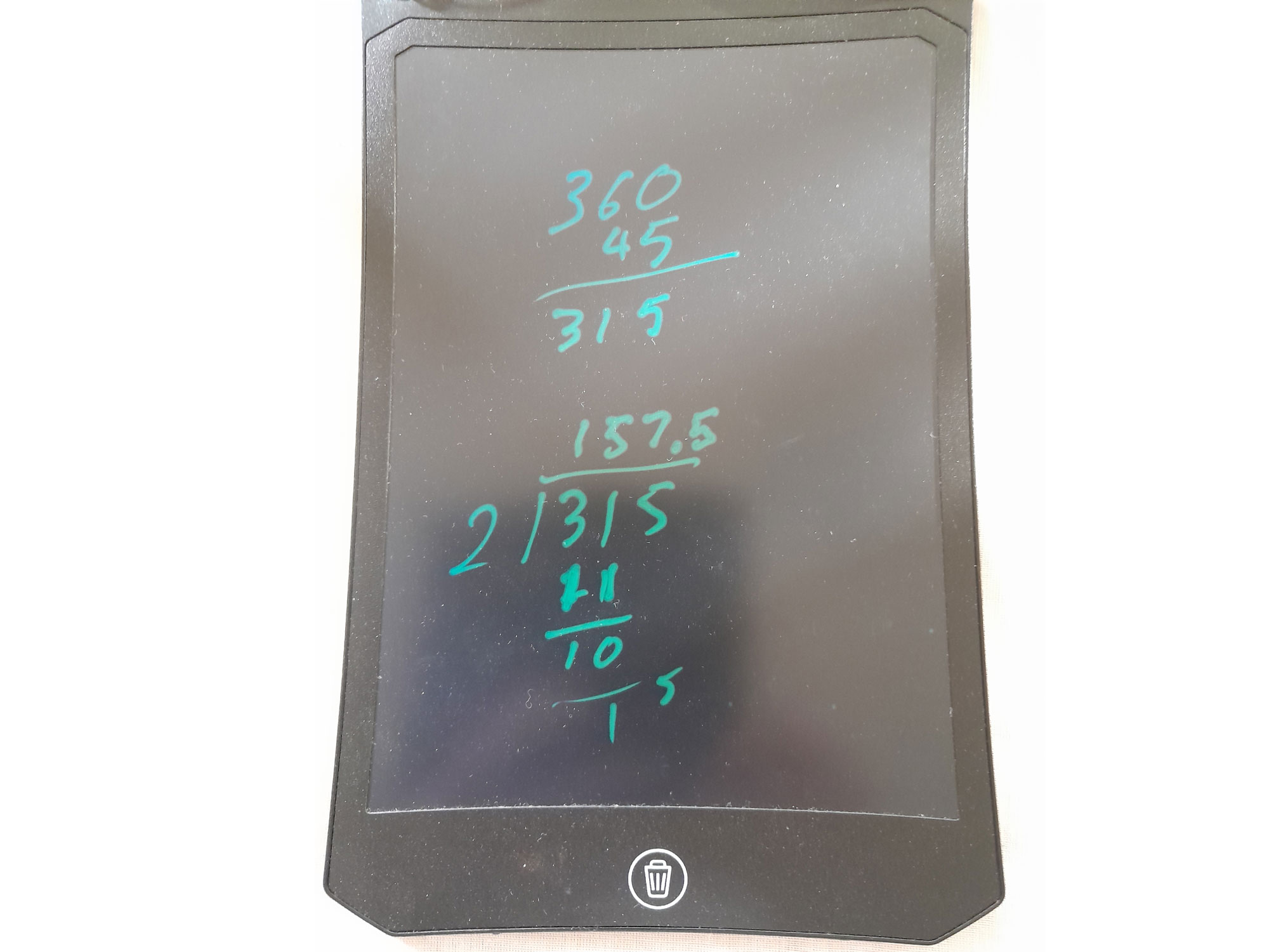
- In passing, a LCD writing pad such as this one is great for doing calculations etc. and doesn’t waste paper. You can save your calculations, or simply clear them, ready for the pad’s next use.
- I measured off all the other lengths required and cut them, then lined up the four legs, cross arms, short cross arms, tops and feet in turn to trim each set to precisely the same lengths. Any difference in any of the individual pieces in each set would put the stand out of kilter, even slightly, and could result in hassles in assembling it properly.
- Here are all the pieces cut to length and ready for assembly.
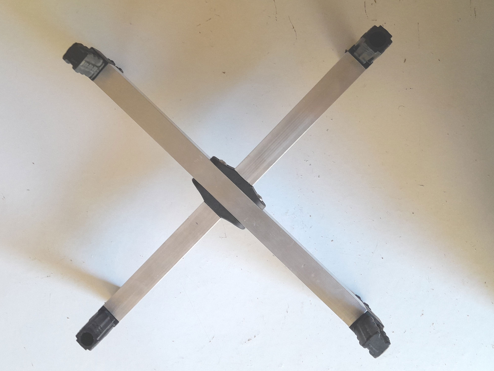
- I did a dry fit of the cross arm assemblies to ensure that once assembled, they would each be 360mm from end to end across both axes.
- Here are the respective lengths of the top (left) and the slightly longer foot (right). Upon reflection, I could have made the feet longer, but they do work fine as is.
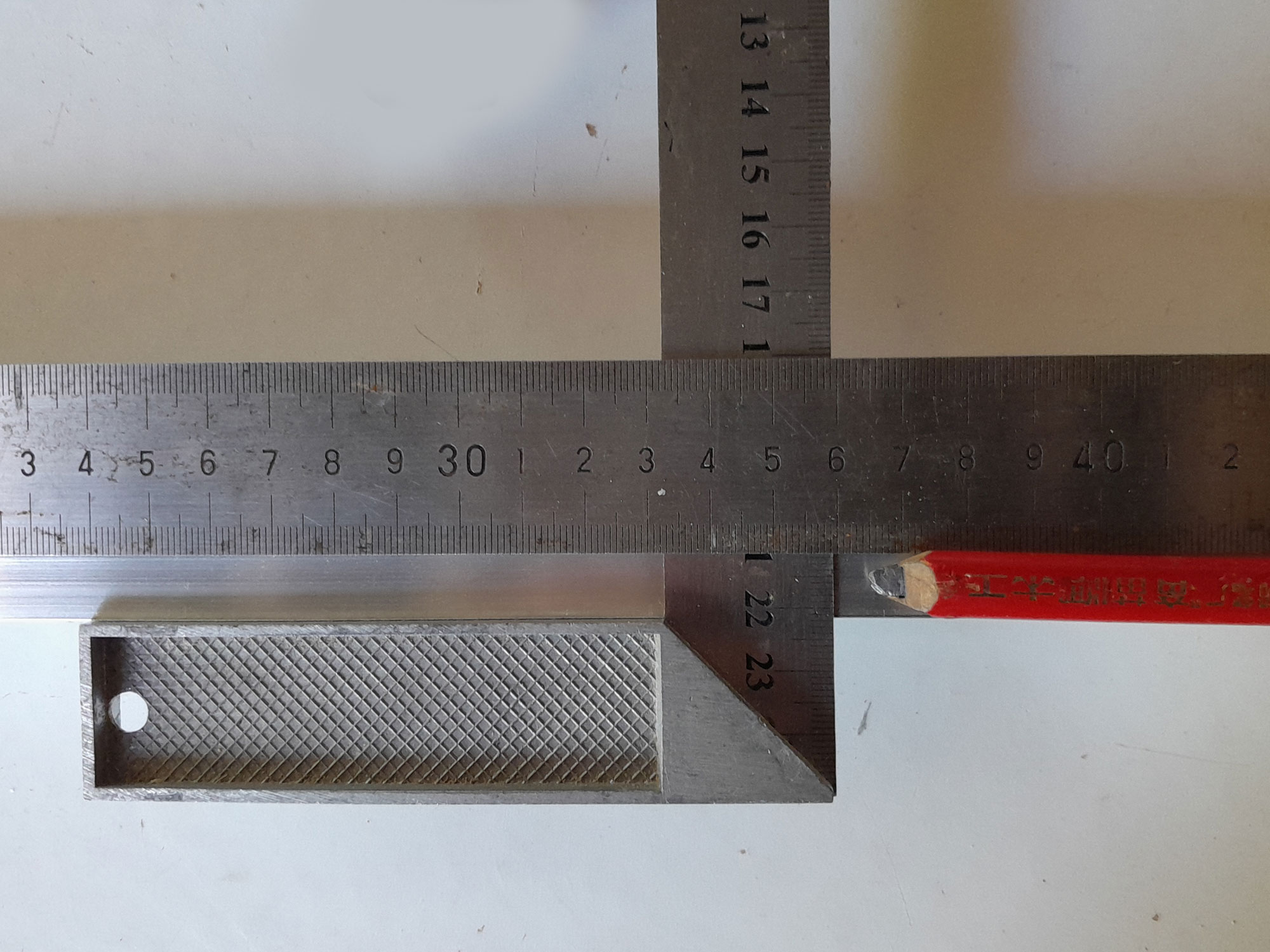
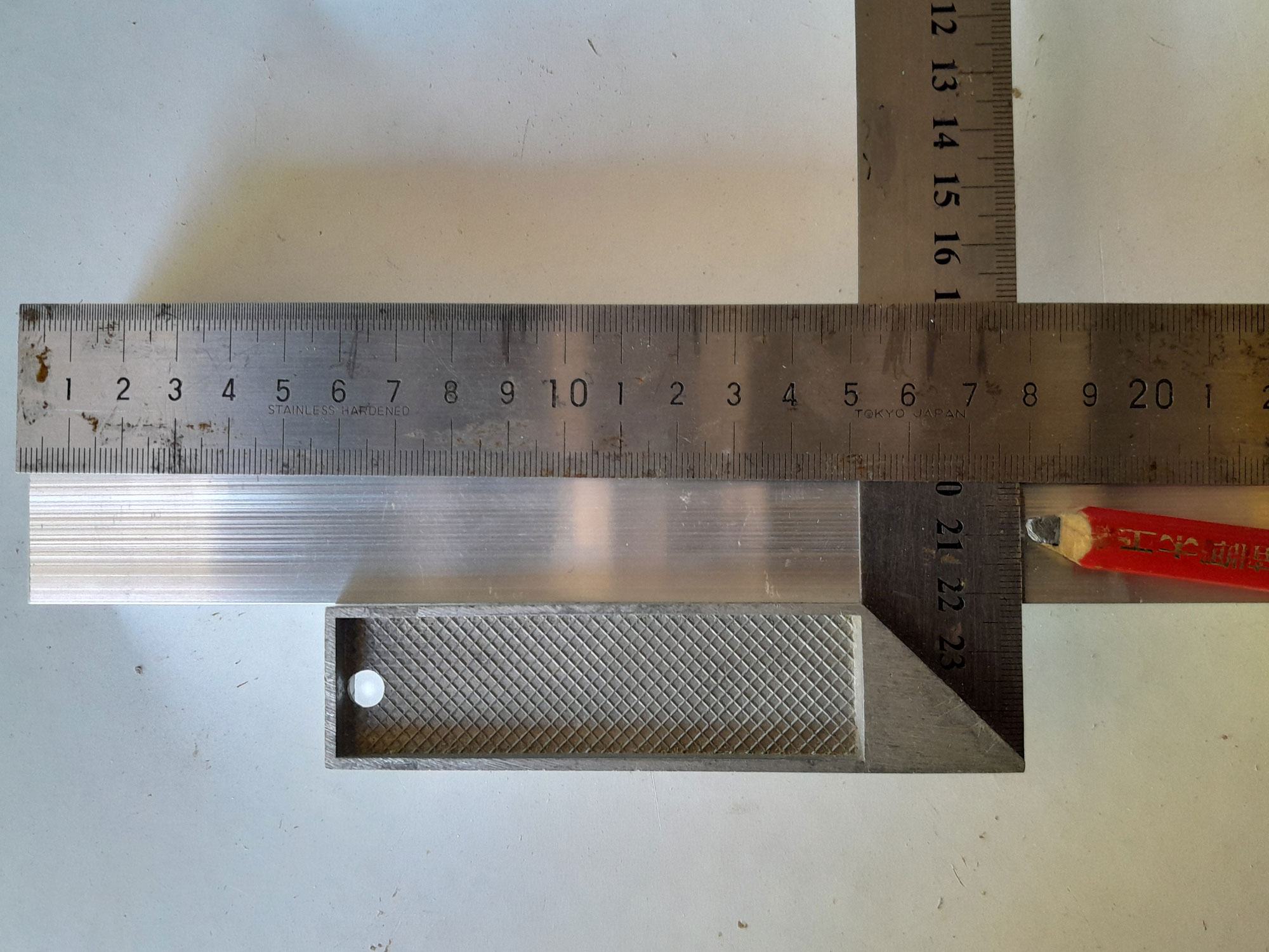
- I measured and marked the centre line of each long cross arm – 180mm.
- Then I VERY carefully measured the spacing for brace securing screws – 26mm from the centre, as it turns out.
- Then I measured the 26mm from the centre line on each long cross arm.
- You can use a centre punch designed for use with a hammer, or a spring-loaded version, and a gauge to ensure you mark (indent) the exact centre point for each securing screw.
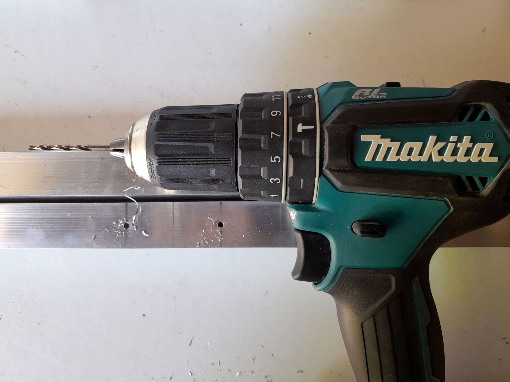
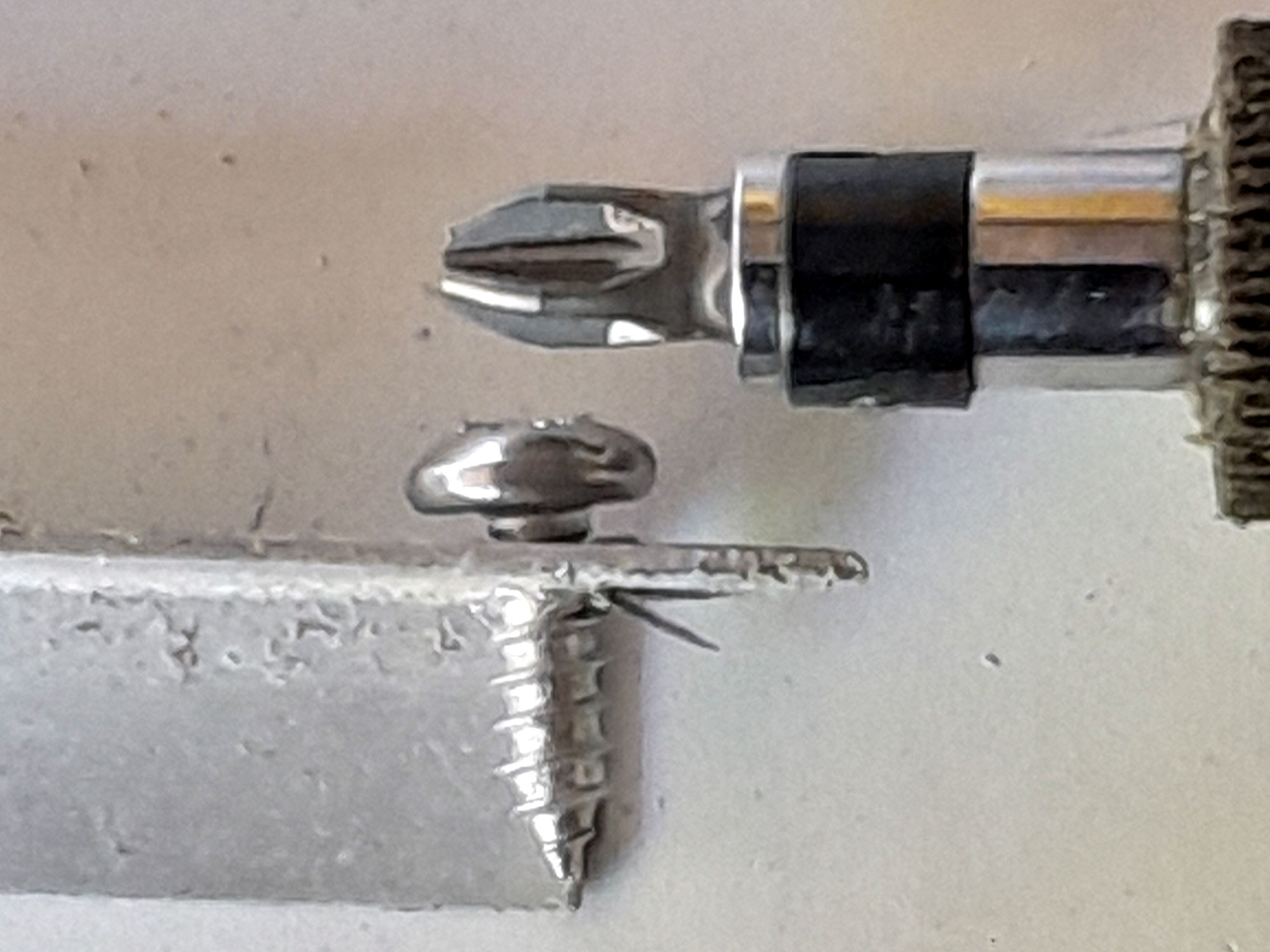
- Having marked (indented) the centre points, I drilled a 4mmØ pilot hole for each securing screw.
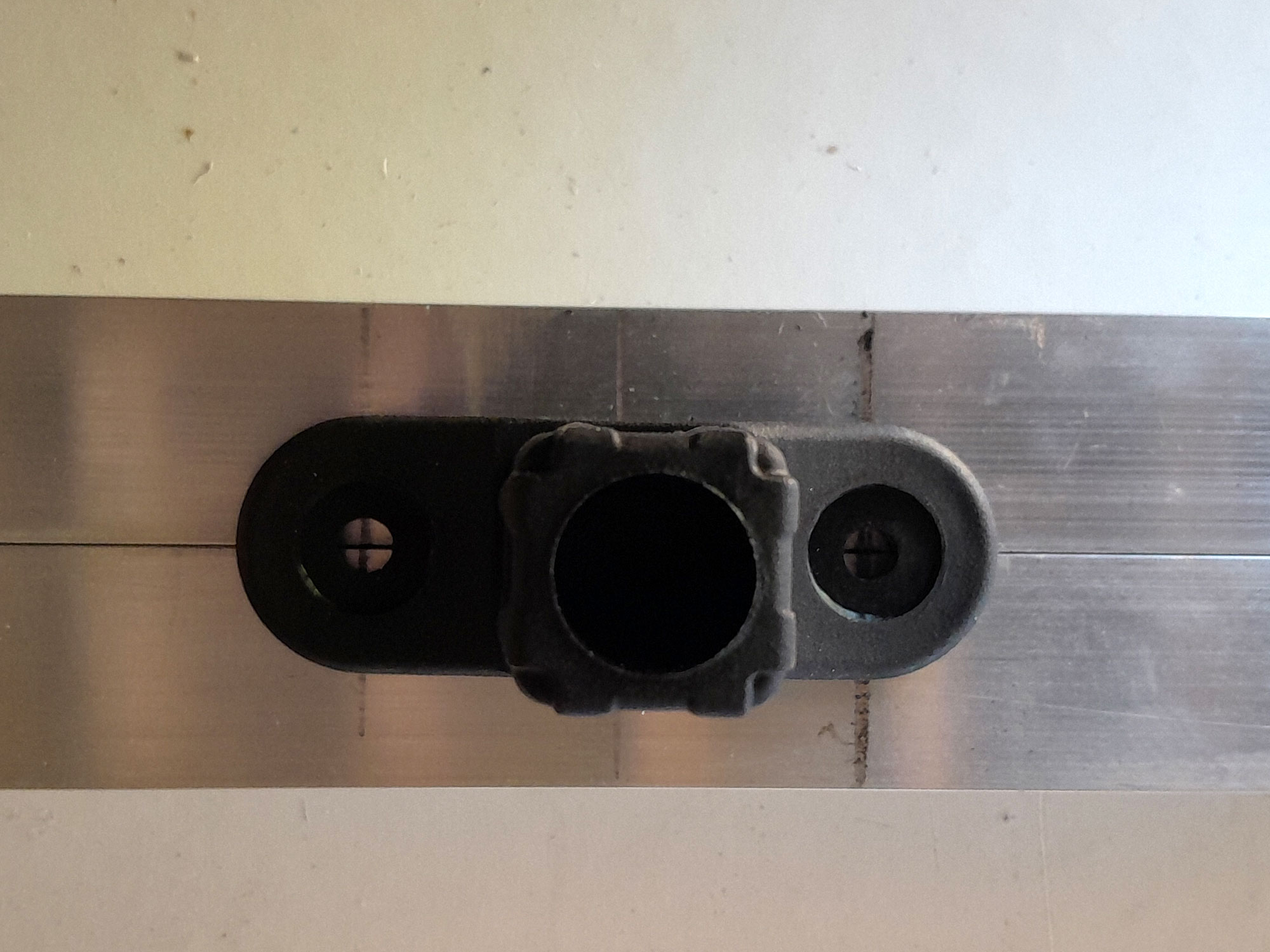
- Here you can see they are both precisely aligned with the brace.
- Just before securing the braces in position, and using a piece of scrap aluminium, I confirmed the 4mmØ pilot hole was the correct size.
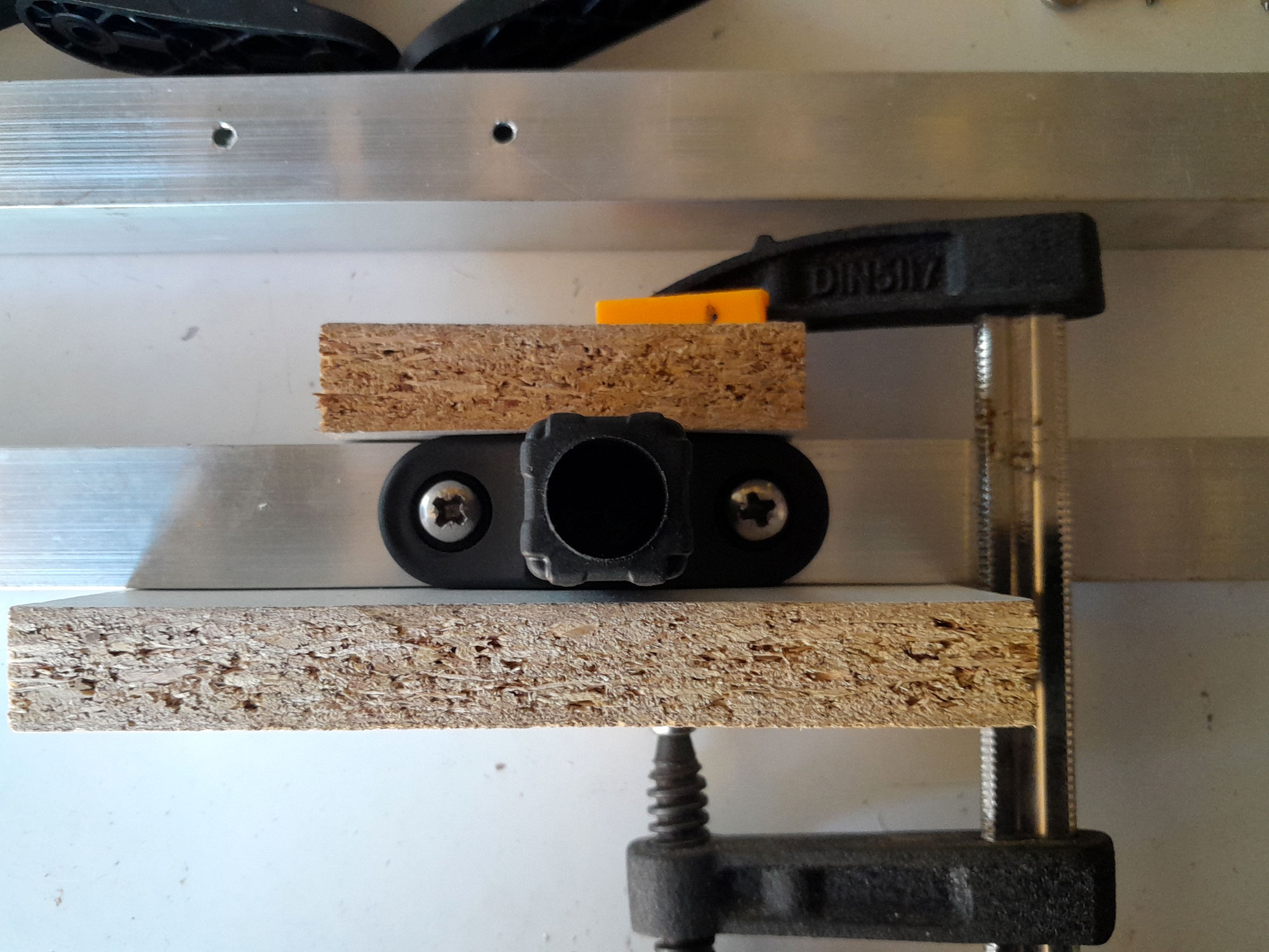
- To ensure that the braces were perfectly aligned, I clamped them on the cross arm and used a couple pieces of scrap chipboard to ensure the brace was perfectly aligned and held securely in that position, and drove in each securing screw.
- Job done!
- Then I used a wooden mallet to seat each T connector. Just make sure that they are properly aligned… believe me it is too easy to fit them and 90º to each other – that’s when you turn the air blue, and neighbours take their children indoors. If that should happen – wrong alignment, not the kids being yanked to safety and out of earshot – you will need to tap the offending connector out and reseat it.
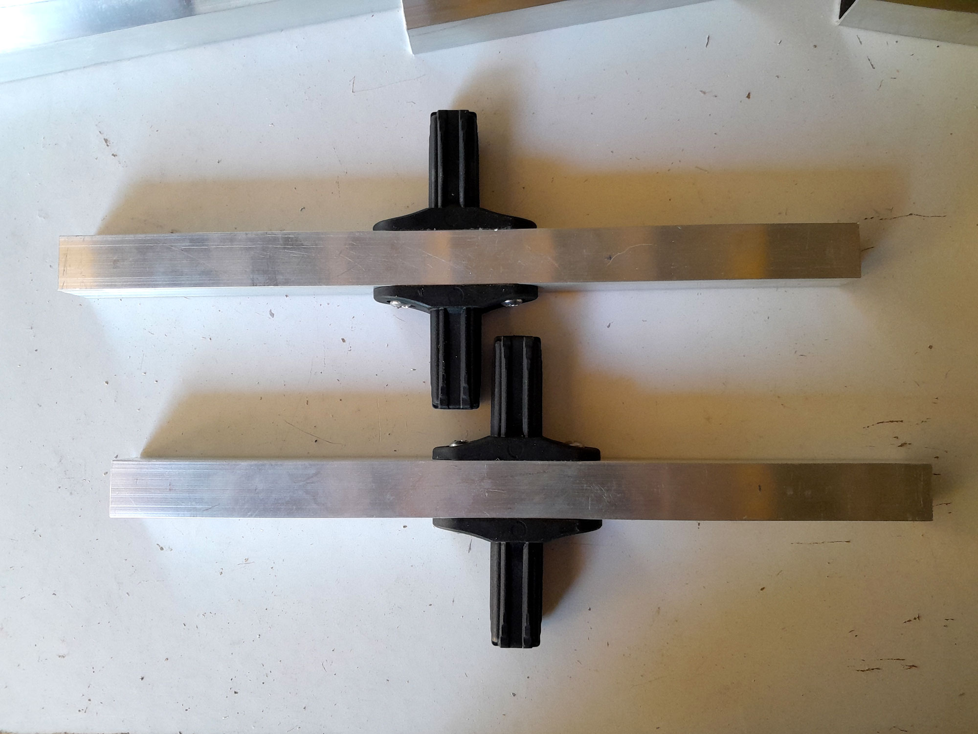
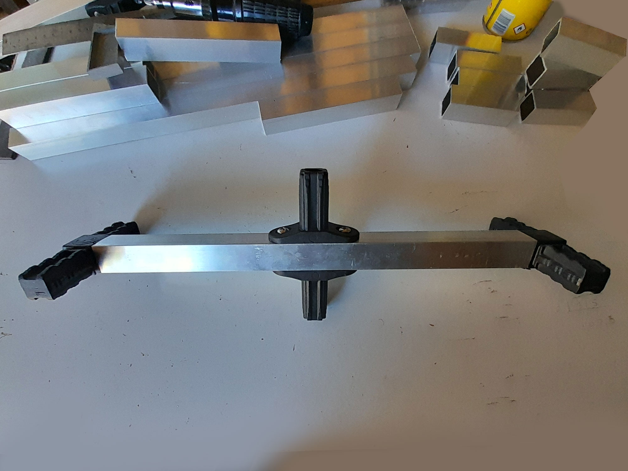
- One of the cross arm assemblies complete… looking rather like a four-prop drone main frame.
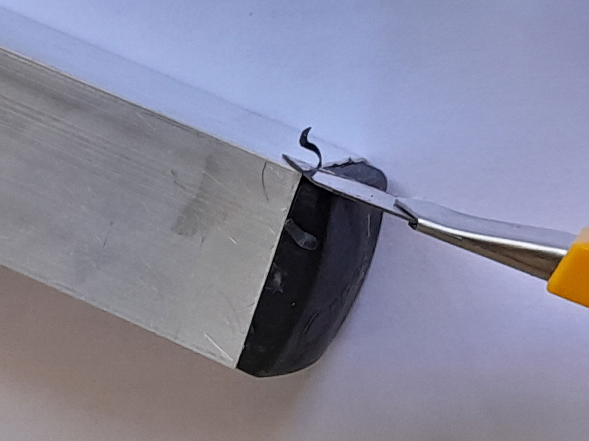
- I then completed the assembly and tapped in the end caps. Then I used a utility knife to remove any little bits of the connectors and end caps material shaved off during the seating process. Note: When assembling the stand, if you attach the legs to each cross arm assembly and then seat them, you must ensure that you keep the seating lengths as even as possible, tapping them down in rotation, because if you seat one side completely and its matching mate on the other side is not, you stand the risk of either bending the aluminium and/or causing the connectors to over-flex.
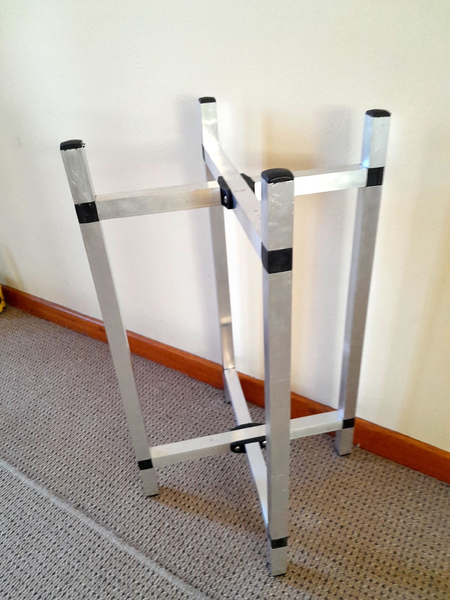
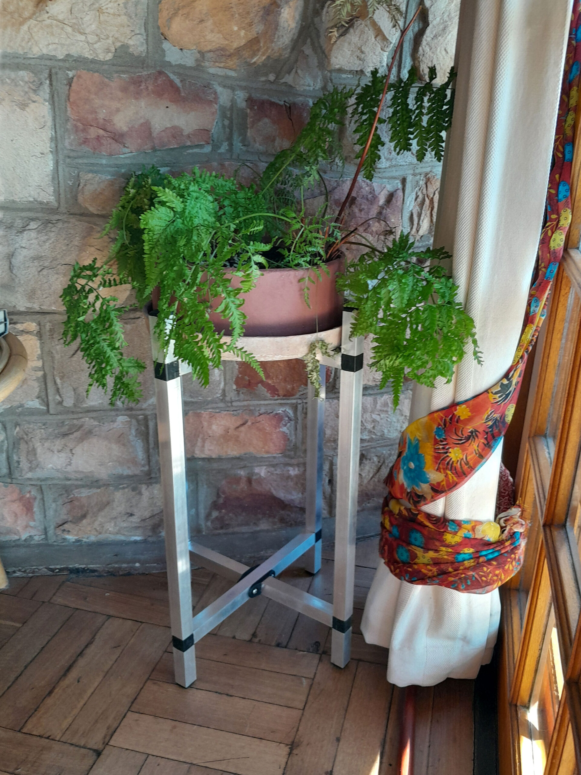
- The completed stand. Here it looks quite utilitarian, but you need to visualise it with a trailing pot plant or one with long fronds draping themselves down it.
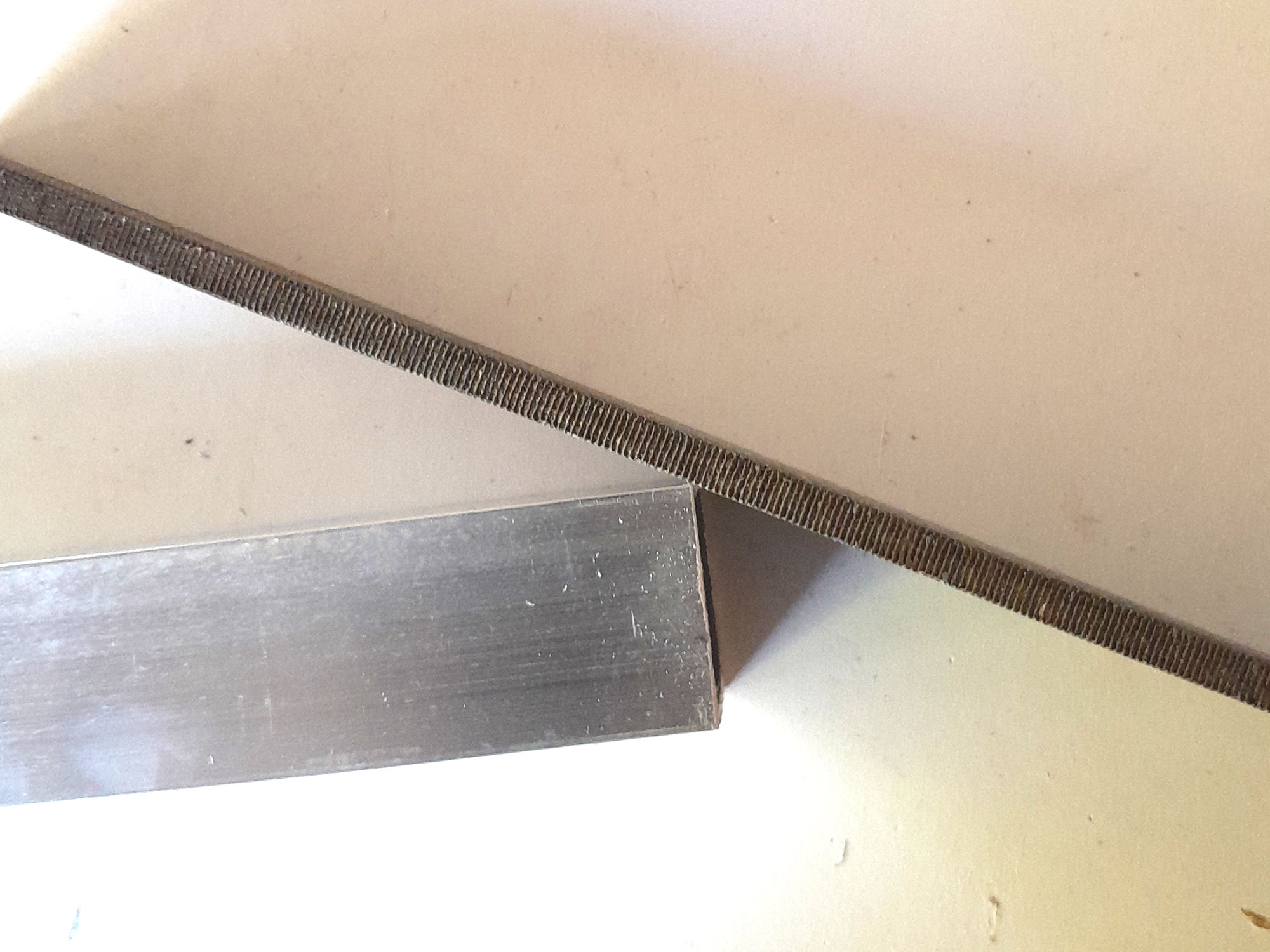
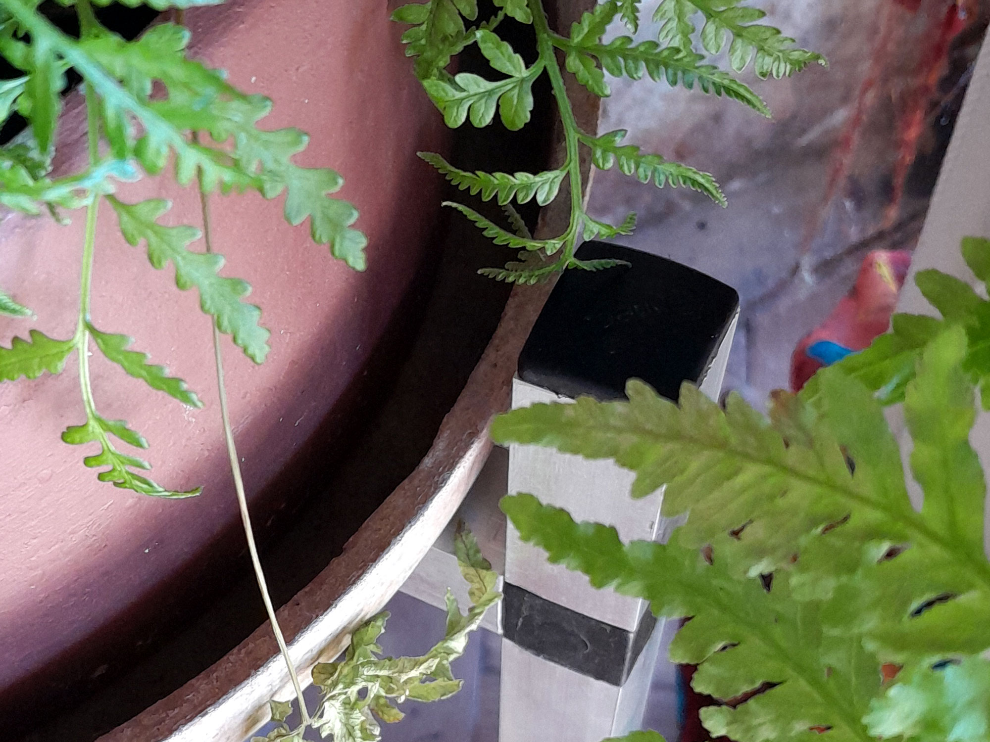
- Here is a close-up of how the tray fits within the stand.
- The completed stand, doing what it is designed to do.
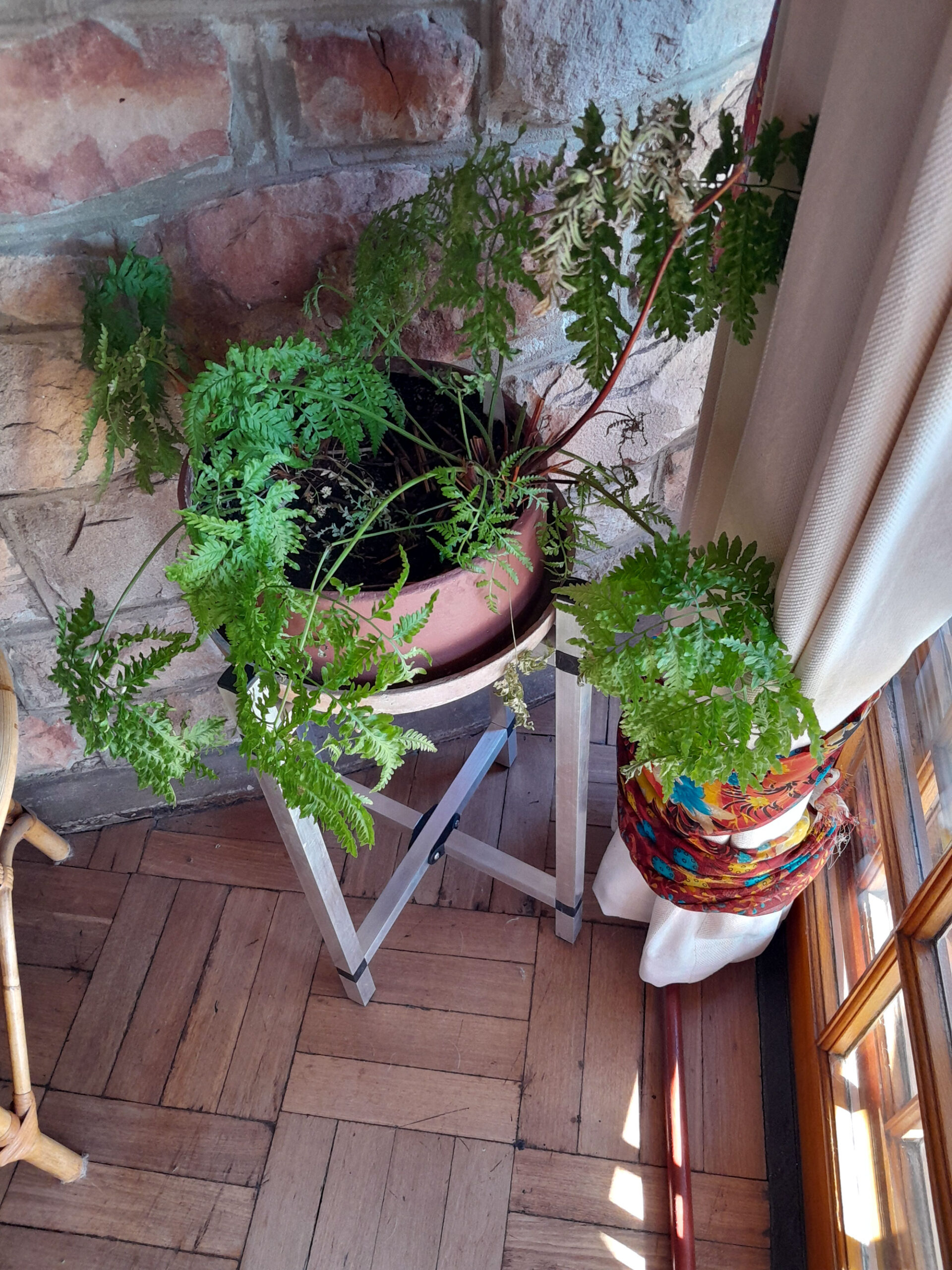
- And another view from the top.
Tools:
Drill/driver (mains or cordless), 4mmØ drill bit, hacksaw, jigsaw fitted with metal-cutting blade, or circular saw/mitre saw fitted with a blade for cutting aluminium, centre punch and hammer, or spring-loaded centre punch, gauge, wooden mallet and/or bar clamp.
Project guide
- Difficulty: Experienced
- Estimated time: about a full day
- Cost: Depends on the cost of the materials from your Mica and the dimensions of the stand, but for the example featured here, about R500
These materials are available at selected Mica Stores, or your local Mica should be able to order them for you, or be able to suggest a supplier. To find your closest Mica and whether or not they stock the items required, please go to www.mica.co.za, find your store and call them.