06 July 2022
 within easy reach)
 within easy reach")
Put those pots, pans and dishes (and trays) within easy reach
This is actually in principle a very simple project, but also very easy to get wrong if your measuring is just a millimetre or so out, so now, more than ever perhaps… measure three times, and cut once.
Chipboard cupboard shelving is available in the following range:
- 2750x225x16mm
- 2750x455x16mm
- 2750x530x16mm
- 2750x600x16mm
However, please note that this product is also available in sheets, from which shelving of bespoke widths and lengths can be cut and edged.
- 2750x1830x12mm
- 2750x1830x16mm
- 2750x1830x18mm
- 3050x1830x12mm
- 3050x1830x16mm
- 3050x1830x18mm
- 3660x1830x12mm
- 3660x1830x16mm
- 3660x1830x18mm
And it is available in thicknesses in the following range: 12mm, 16mm, 18mm, 22mm, 25mm, 28mm, 32mm, and 40mm.
Also note that it is available in a range of colours; in this instance, I stuck with white and with the 16mm thickness to match the original shelf.
The use of runners as in this project only really come into their own when dealing with lower shelves 455mm and wider; the rear void of narrower shelves in the 225mm and 305mm range is far easier to no matter how low they are.
A note on the sliders
I could have used self-closing drawer runners, which are very good for their designed purpose and commonly used in conjunction with desk drawers, dressing table drawers, and kitchen cabinet drawers and so on. However, I felt there could be too much weight on the ends when these drawer-trays were fully open and loaded with dishes and so on as the weight would be concentrated over only about 50mm or so when the drawer-tray was fully open. The ball-bearing slides used here have more ‘length’ to bear the weight of the drawer-tray and its load and these slides with ball bearings have a weight capacity of 25kg – more than ample to handle the load. They also have the advantage that when fully open, the entire drawer-tray is exposed, making accessing the contents very easy.
In passing it almost goes without saying, but this idea can be adapted to just about any cupboard or cabinet with shelves.
MICA—DD-13

MICA—DD-14
MICA—DD-15
MICA—DD-16
MICA—DD-17

MICA—DD-18
MICA—DD-19
MICA—DD-20

MICA—DD-21

MICA—DD-22
MICA—DD-23

MICA—DD-24
Materials:
- BisonBord® 16x450mm wide – four lengths 860mm long. (Note that the material I used was 450mm wide, and not 455mm)
- SA pine:
- 9x44mm cover strip – eight lengths 860mm long (four front-pieces, four rear backstops)
- four handle reinforcing strips, each 200mm long
- Handles – four brushed satin – plus eight 4mmØ flat washers
- Ball bearing slides (zinc finish) – four 500mm sets. Maximum weight bearing should not exceed 25kg
- 6 gauge 16mm attachment CSK (countersunk) chipboard screws (but you can use 6x16mm pan-head screws as an alternative) to attach the slider bodies to the sides
- 8 gauge 35mm CSK chipboard screws to attach the slider sections to the ends of the drawer-trays
- Front cover strip attachment screws: 24 6x25mm pan head self-tapping screws; 12 38mm
- Rear backstop cover strip attachment screws – 40 6x25mm CSK chipboard screws
- Aluminium 19x19x1.5mm extrusion – two lengths of 2.5m, cut to eight lengths of 450mm.
- Wood glue
- Finish of your choice – I used high-gloss enamel for the front cover strips and rear backstops.
Method:
- Here’s the cupboard before the adaptation… the items on the shelf are quite easy to reach, but those in the bottom of the cupboard, less so… particularly any right at the back.
- First step is to measure the space taken up the doors.
- And of course, the hinges. In this case, around 22mm. Obviously, the drawer-trays would have to be able to clear these obstacles if they were to be opened completely. Otherwise, what’s the point?
- The width of the cupboard was 920mm. Ensure that you measure and check this measurement to the millimetre.
- The shelf depth was 550mm
- And the height to the underside of the countertop 722mm.
- However, there is an upper cupboard panel and this must be taken into account. Therefore the total available height is 722-16 = 706mm.
- I began by making complicated measurements and which drove me mad. I initially made the clearance 27mm, to allow more than enough clearance for the slides past the hinges.
- I repeated the process on the other side, and holding the end of the tape on the line on the other side, ended up with the total length of each drawer-tray of 867mm, plus the slider width, plus the aluminium angle drawer-tray support (more about that below).
- Then sanity prevailed, and I did what I suggest you do… I placed an offcut of 16mm shelf against the side of the cupboard, and placed a slider against it, and easily confirmed that the latter, when extended, would clear the hinge. (There is no problem with clearing the door as the hinge is deeper.)
- With the slider extended I used a small offcut to mark off its inner edge from the inner surface of the existing cupboard. I repeated the process on the other side, and was then able to come up with a definitive drawer-tray length of 860mm, which takes into account the thickness of the 19x19mm angle aluminium (1.5mm) on each end of the drawer-tray, plus that of the two sliders, plus that of the two insert sides.
- These sliders as mentioned are rated to carry a maximum load of 25kg. So as a precaution, I weighed one.
- It came out at perhaps a fraction over 3.5kg – or 1.75kg per side, so that allows a total load of around 21kg per drawer-tray – and that is an awful lot of pots and pans!
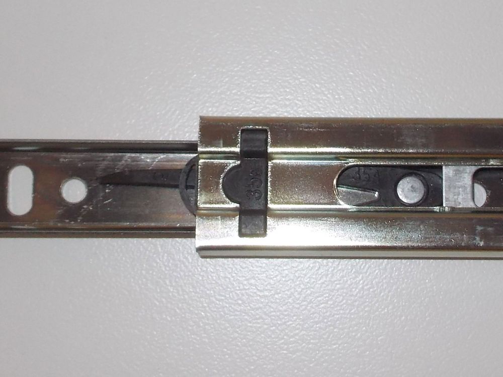
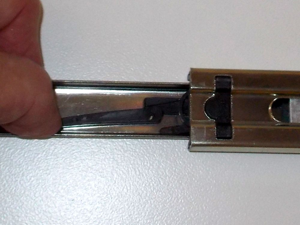
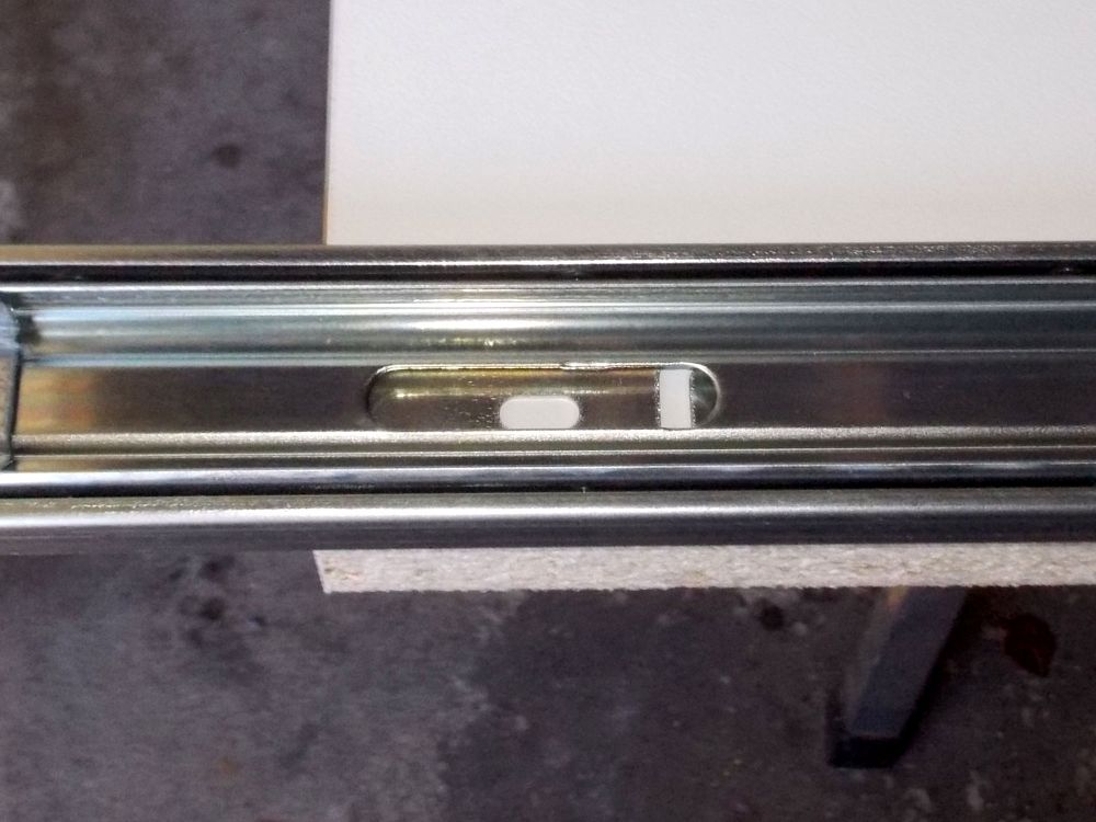
- The first step was to attach the sliders to the sides, and the first measure before doing that was to separate the outer section (that which will be attached to the drawer-tray) from the main body (that which will attach to the side). Fully extend the slider to expose a plastic lever. Flex it to release the slider outer section and put it free.
- Like so.
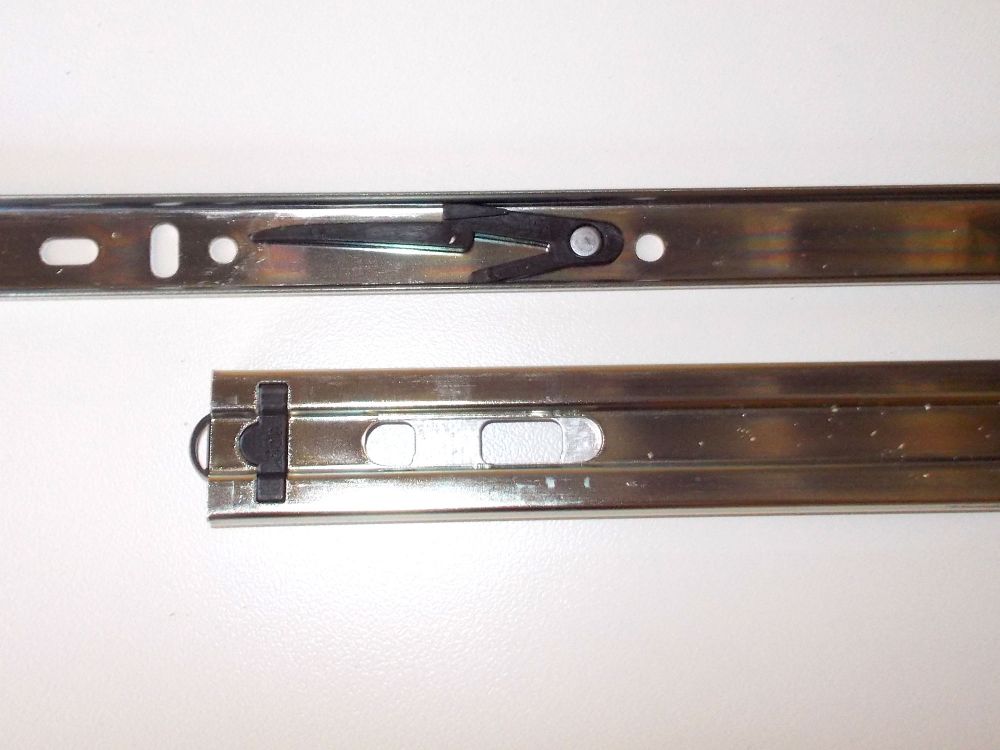
- Separation complete, with the lever clearly visible. When reinserting the slider, simply push it in and the lever is flexed and then snaps back into position as the stop passed over it.
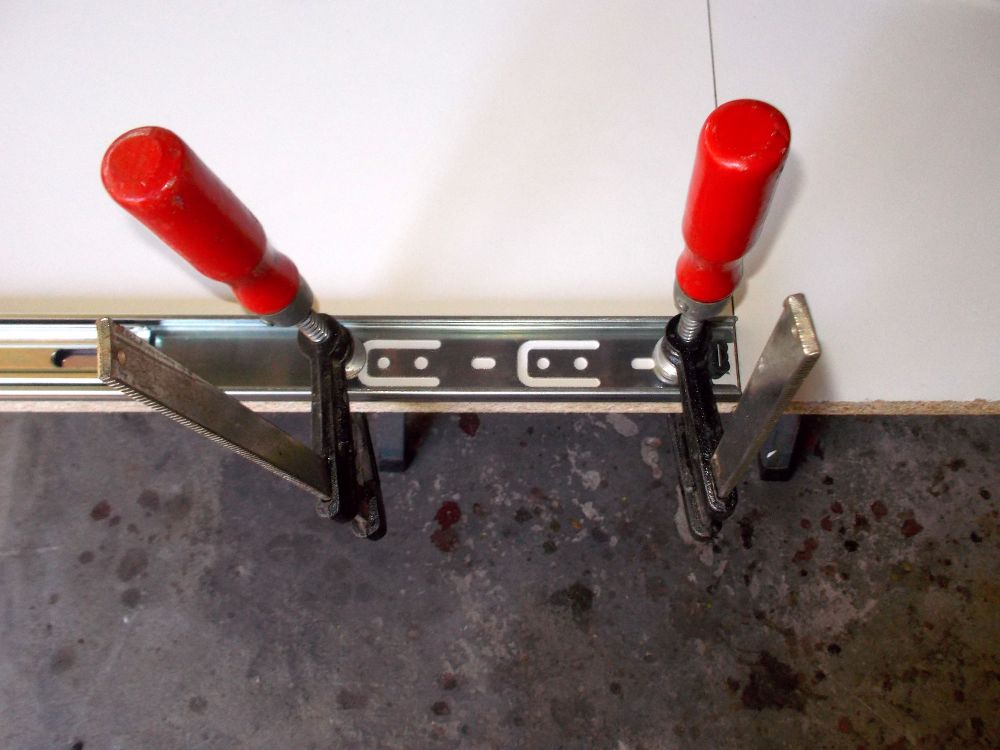
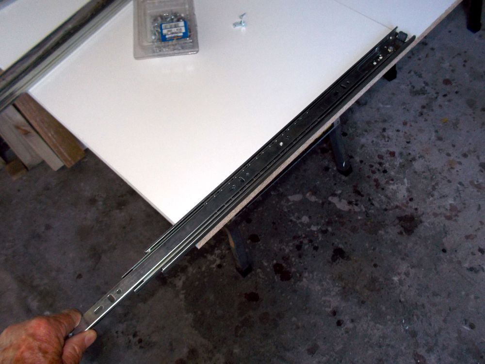
- I lined up the sides and clamped them together and then positioned what would be the bottom slider against the bottom edge of the side. A piece of offcut as shown here makes lining up the slider bottom edge with the side’s bottom edge very easy. Note that the slider’s end lines up with what will be the rear edge of the side.
- Pulling the second section of the slider out, I clamped the slider body in position, taking care not to exert any force where it might deform the slider body.
- The second section has apertures cut into it and is moved back and forth so that the attachment screws can be driven into the wood at the appropriate spots.
- With the second slider section shifted, the other attachment screw positions are exposed.
- I attached the slider body to the side first at the rear.
- Like so. I used CSK screws as they would self-centre themselves in the holes in the slider body, but the screws must be precisely centred so that the slider body does not shift when the screws are driven in. you can use pan head screws if you so wish.
- I repeated the process with the attachment screws at what would be the front of the side, and checked that the slider’s second section moved freely.
- It is as well to check for free movement as you drive in each screw, so that if you fail to drive one in fully, or it is out of kilter, you will know which one it is, and be able to make the correction.
- With the first slider body secured, I ensured that sides were still precisely lined up, and then used a couple of offcuts to sandwich the slider’s opposite number in position to line them up precisely. Caution: Do NOT over-tighten the clamps in case you distort the sliders. They are precision-made. You need to apply just enough clamping pressure to hold the sliders in position, and precisely lined up.
- I repeated the attachment procedure on the second slider as I did with the first.
- Then I checked that they lined up and were in a perfect straight line. They were – and are! I temporarily reinserted the outer slider sections and checked for full and smooth movement. Then removed them again for later attachment to the drawer-trays.
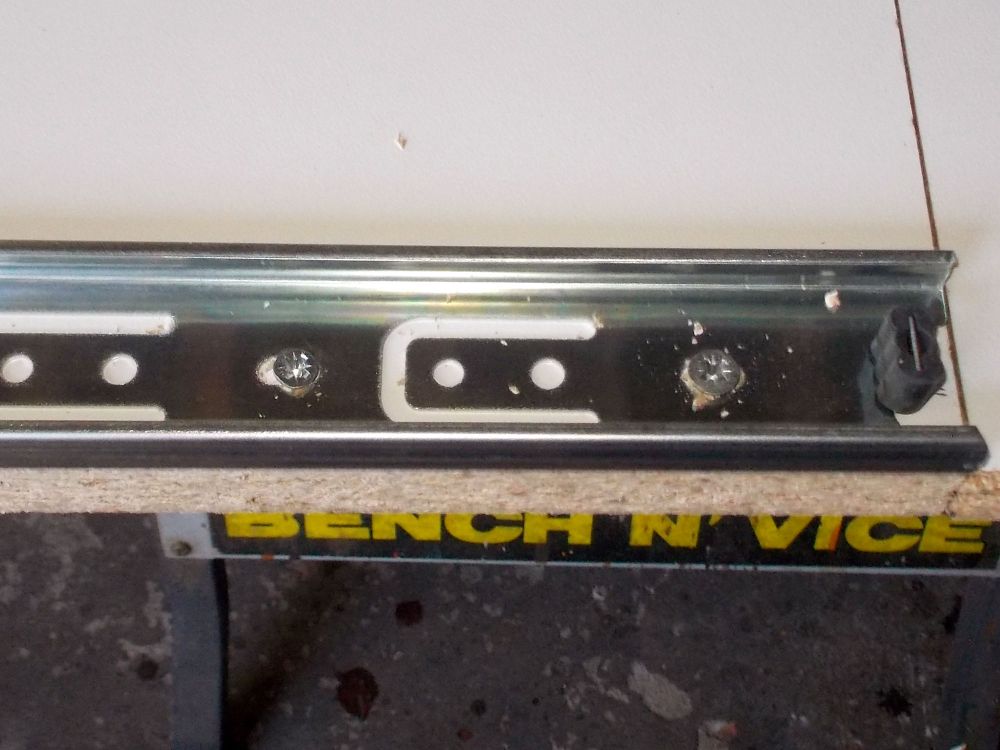
- This shows one of the attachment screws at the rear end of the slider.
- And here are two at the front edge.
- I used four screws at the front end of each slider and two at the rear. This is because with the drawer-trays fully out, there could be a significant force on the front attachment screws, so the more the merrier to take the weight.
- Next step… it’s no good making a mistake with the drawer-tray spacing, so I did a quick check of every conceivable kitchen utensil that would go on the drawer-trays. From sieves, to pots, pans and pressure cooker. That ensured I could set the shelf spacing for most efficient use. And they could be set to quite close tolerances… a gap of 5mm above the tallest utensil would be quite sufficient, because you would be pulling the drawer-tray out to access from directly above whatever you needed and not pushing your hand and arm into a shallow space blindly.
- I positioned the drawer-trays as follows:
- I positioned the drawer-trays as follows:Bottom drawer tray – flush with bottom edge of side.
- Second drawer-tray – gap of 270mm (for the deepest, bulkiest utensils such as a pressure cooker.
- Gaps between second and third drawer-tray – 130mm each.
- Gap between top drawer-tray and underside of counter – 100mm (as this drawer-tray was intended for storing trays, cutting boards and the like).
Naturally, you would select your own drawer-tray spacing depending on your storage needs.
- I positioned and attached the other three sliders on one side and then, using straight offcuts to ensure proper alignment, fixed their companions to the other side, as always checking for full and smooth movement after each screw was driven in.
- Note that I again lightly clamped each slider body to the straight timber to keep it in place during the attachment process.
- Now for the drawer-trays themselves… I used the drawer-trays themselves to mark the cut lines precisely.
- I began by cutting the front-pieces and rear backstops each to 860mm to match the drawer-tray lengths.
- I bevelled the ends at 45°… my artistic flourish.
- I selected brushed satin handles for each drawer-tray.
- During the cutting of the front-pieces and rear backstops, I also cut four handle reinforcing strips, each 200mm long. And bevelled them at 45° on each end as you can see, just for a better appearance.
- Although these sliders I used in this project open and close very, very smoothly, I wanted to ensure that the front-piece would withstand any sudden yank on any of the drawer-trays. Hence the reinforcing. I glued the handle reinforcement piece to the centre of each front-piece and secured each with clamps until the glue had cured.
- I used a utility knife to remove any glue that had oozed out of the join.
- An old belt sander belt works well to initially smooth the surfaces.
- Then I sanded down all the surfaces, of all the front-pieces and the rear backstops as well for a smooth finish.
- Next step was to drill the holes for the handle attachment screws. I measured the distance from centre to centre. Note how I have used the tape from the 100mm mark, giving a distance between centres of 96mm. You can find doing it this way more accurate when making these sorts of measurements rather than using the tape stop. Just ensure that you do not space the attach screw holes at 0mm and 196mm!
Of course, you can also do it the easy way by simply checking the handle’s package labelling – which very clearly states the 96mm spacing. - I was going to use 4mm flat washers to spread the load when the handles are used, so I needed to use a 16mm scrap to ensure that the washers would clear the surface of the drawer-trays.
- I marked off the handle attachment screw positions and checked and rechecked them for accuracy.
- Then I drilled one pair and lightly attached the handle to ensure it was lined up correctly. Then I removed the handle and used this first front-piece as the template for the other three. Hint: The attachment screws are 4mmØ, but I drilled 5mmØ holes. this ensures you have a little ‘wriggle room’ when finally aligning and securing the handles – and the 4mm flat washers ensure that there is sufficient surface on the inner screw-head side to ensure a firm, secure fixing.
- Now for the rear backstop and front-piece securing screw holes. I used a piece of 16mm scrap (which matches the drawer-tray thickness) to position the attachment holes 8mm in from the edge.
- I drilled the outer holes 30mm in from each end and then spaced the other seven holes along the space between.
- I drilled the pilot holes using a 1.5mm bit.
- Then I used this first front-piece as the template for the other three and for the rear backstops. Only do this if you are certain you can drill very accurately. If not, then mark off and drill each front-piece’s holes individually – it is important that they all present a uniform appearance because they will always be on view when the cupboard doors are open.
- Oops! I found out that the two holes on either side of the centre attachment screw were far too close to the ends of the handle reinforcing strip, so I repositioned them in towards the centre by 30mm. I filled in their original pilot holes and sanded them down when dry. No harm done. You see, I make these mistakes do you don’t have to.
- The completed rear backstops (top) and front-pieces (bottom). Do I hear you ask why rear backstops? Well, simple, really… if a drawer-tray is pulled open very quickly you don’t want its dishes etc to cascade off the rear edge. See? I told you it was simple. At this stage I did a final sanding and then applied high-gloss white enamel. I applied four coats to each piece, lightly sanding the first, second and third coats, with the final fourth coat applied with a sponge roller. Don’t forget to also paint the rear surface of each front-piece as they will be fully visible when the drawer-trays are fully extended. The rear surface of the backstop can probably get away with just a couple of coats as it will not generally be visible, but the forward-facing side will – and so need the full treatment.
- Now for the aluminium angles… I set it against the end of one drawer-tray.
- Then I used an offcut of 9x44mm cover strip to set the cutting line.
- Here’s the reason for using the 19x19x1.5mm aluminium angle… with a normal fixed shelf, the support is underneath (detail shown lower left), so the weight of the shelf and its contents is taken by its full 16mm or whatever thickness of material. But when using sliders, as I have done, the attachment screw passes through the middle of the material, so in this case there would be only 8mm above it to take the full weight of the shelf and its contents. Doing it this way ensures that the full 16mm of the drawer-tray is fully supported along its full width. Crafty, eh.
- I used a hacksaw to cut each length.
- Then I used a fine metal file to smooth and neaten the ends.
- Here’s the slider section and its aluminium companion.
- This was my first method… I lined up and clamped the slider section to its aluminium angle, using a wood cushion to avoid damaging the slider.
- Then I clamped the pieces, still clamped together, to a couple of lengths of 22x44mm SA pine.
- Then I drilled four 4mm holes through the aluminium.
- Then I woke up, and slid the aluminium angle under the edge of the drawer-tray, used a 9x44mm offcut to set the gap, and a 22x44mm offcut to lock it in position.
- I repeated the procedure at the far end.
- Then, holding the slider section firmly by hand. I drilled the four 4mm attachment holes through the aluminium angle. Doing it this way was much quicker than my first method, and also ensured that the bottom edge of the slider section was absolutely flush with the bottom edge of the aluminium angle. I used 8x35mm CSK chipboard screws to secure the slider sections to the ends of the drawer-trays (four per attachment). Then I used an old toothbrush (keep a few in your workshop – they can be very useful) to clear away even the tiniest bit of scurf created when drilling through the aluminium. It is very important you get even the tiniest shards out as they could jam the slider runners.
- Here’s the reason for setting the slider section and aluminium angle forward of the drawer-tray lead edge… to accommodate the front-piece, which rests on the angle aluminium for a neat finish.
- To be neat, the ends of both have to line up precisely.
- The rear end of the slider extends out 50mm.
- A rear backstop fixed in position – note that its end lines up with the inner surface of the aluminium angle.
- The backstop secured in position.
- I used three 6x38mm self-tapping pan head screws at the centre of each front-piece, and 6x25mm screws of the same type along the rest of each front-piece, driving them in just until the pan head base was flush with the front-piece’s surface. So their heads stand proud. Note: I found it easiest to attach the handles to the front-pieces before fixing the latter to drawer-trays – it is much easier as you have ample room for a screwdriver to tighten the handle attachment screws.
- Here we can see two of the three 6x38mm screws at the centre of a front-piece. The third is obscured by the handle.
- Now for the fitting! First, remove the cupboard’s existing shelf.
- Then remove the shelf supports.
- Now position the sides allowing space when the cupboard doors are closed to accommodate the drawer-tray handles (in my case 44mm was more than sufficient and also allowed the drawer-trays to be pushed home fully) and secure the sides in position with four 30mm screws each, two at the top, two towards the base, so that they are secured to the cupboard inner sides. This will ensure that the side cannot tip forward when the drawer-trays are open.
- Moment of truth. Fit the first drawer-tray. Success!
- Then insert the remaining three – even more success – and there is 8mm clearance between the handles and doors’ inner edges. Even more and more success – and a huge sigh of relief, I might add.
- Job done, providing far more storage space – doubled from 1.012m² to 2.024m² – and far more convenience.
- Lots of pots, pans, dishes, colanders – and plenty of room for more.
- Here the drawer-trays are shown progressively extended… the lowest one is fully extended and then the other three partially. Even The Boss is chuffed!
Panel:
These materials are available at Selected Mica Stores. To find your closest Mica and whether or not they stock the items required, please go to www.mica.co.za, find your store and call them. If your local Mica does not stock exactly what you need they will be able to order it for you or suggest an alternative product or a reputable source.
Project guide
TIME: A week to 2 weeks
COST: R600-R1000 (depending on the number of sliding shelves you want to install
Skill: 3 (there is no complex cutting or joinery required, but very precise measurement – and I mean very precise [down to the millimetre if not the half millimetre] – is crucial if the project is to be a success)
Tools required:
Circular cut-off saw, hacksaw, cordless drill/driver, sander.