
Are you being served?
This serving tray is just what you need when you have to deliver a bottle of wine and glasses to your guests, or tea and biscuits, to your guests, of course – but they will probably prefer the former!
Materials:
- Tempered hardboard or plywood – 6mm, dimensions up to you. In this case, 330x195mm
- Handles – stainless steel hollow – one pair 136mm; one pair 220mm
- Easy-slider or felt pads – self-adhesive – 4
- Finish – I chose gloss black
Method:
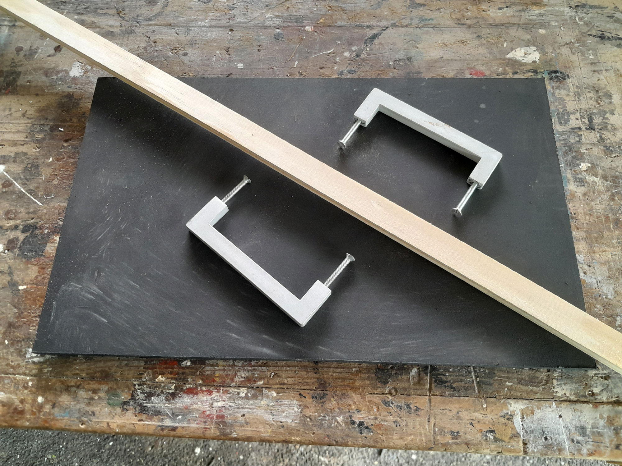
- The materials – the board, an offcut from a previous project has been painted by applying four coats of aerosol gloss black paint.
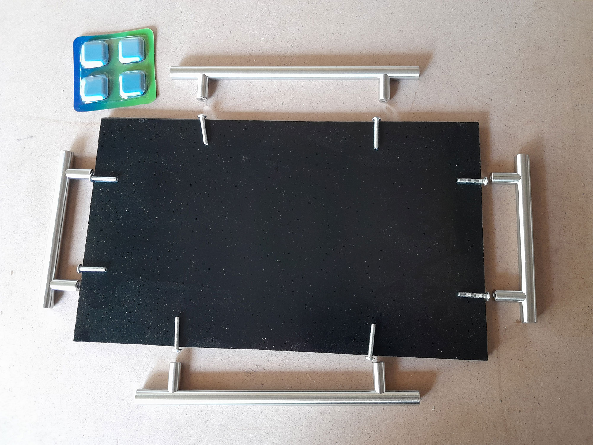
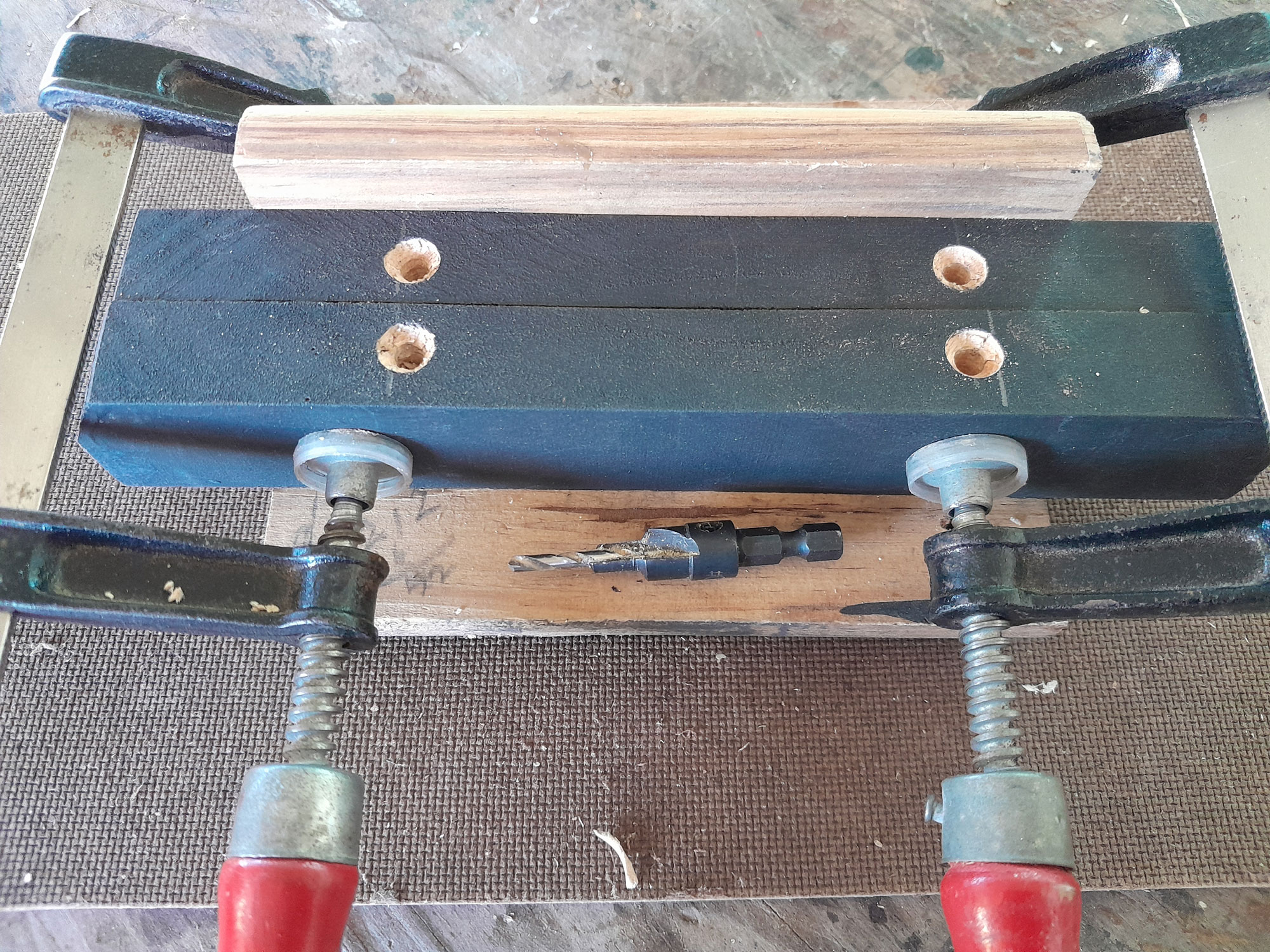
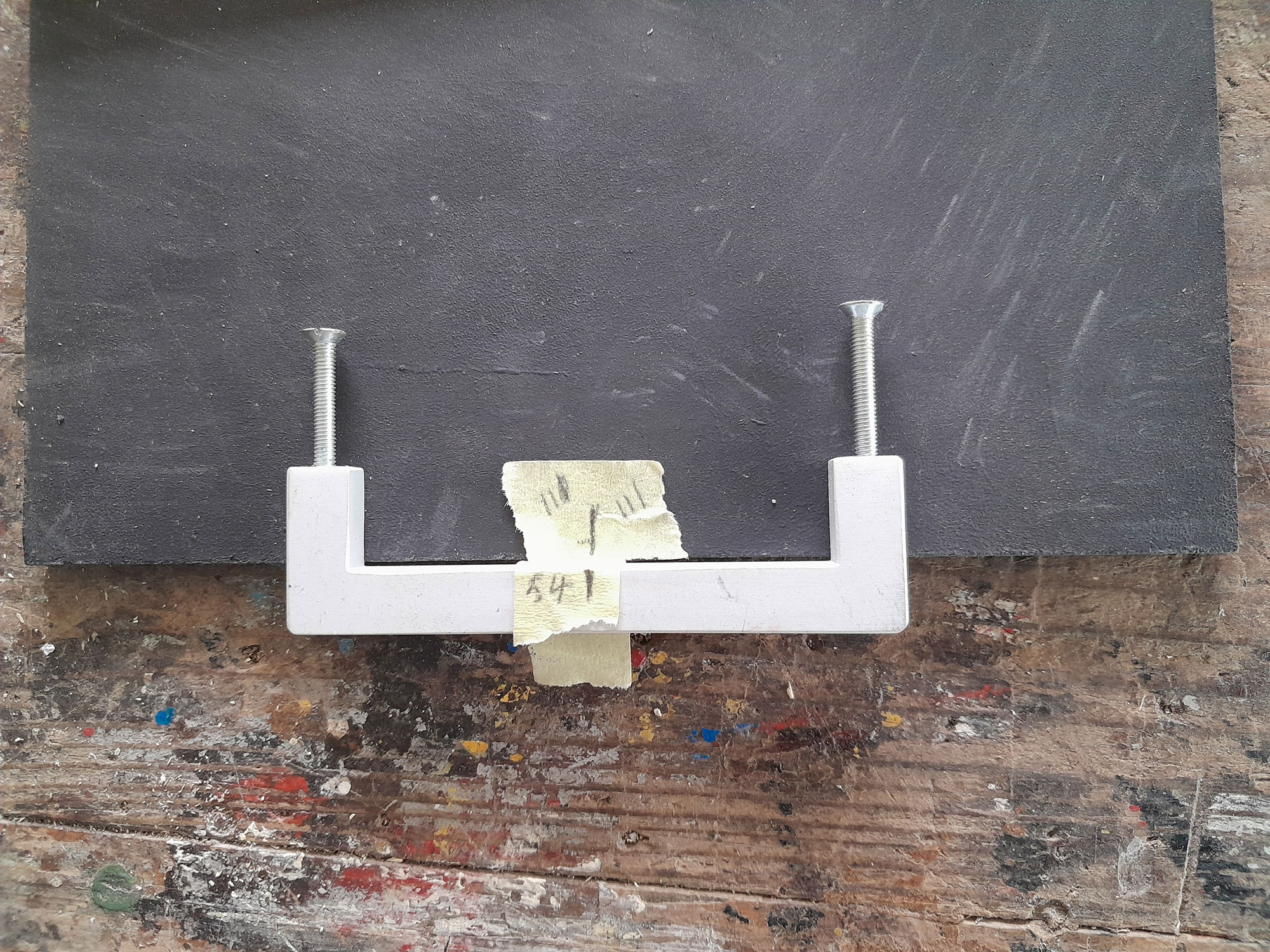
- I used small pieces of masking tape to mark the positions of the handle attachment screw holes, and a gauge to set them exactly 10mm in from the edge.
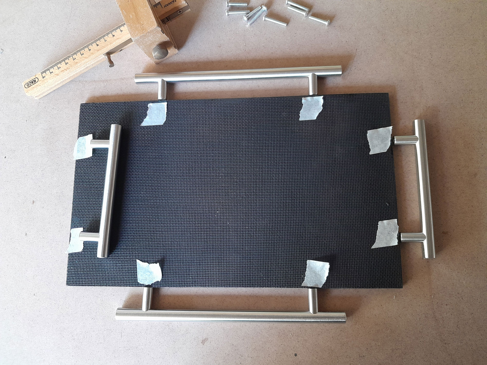
- Then I double-checked the positioning of the holes to ensure they aligned precisely with the handles’ uprights; as with sawing or cutting, before drilling holes for items such as handles, confirm 100% that your measurements are correct.
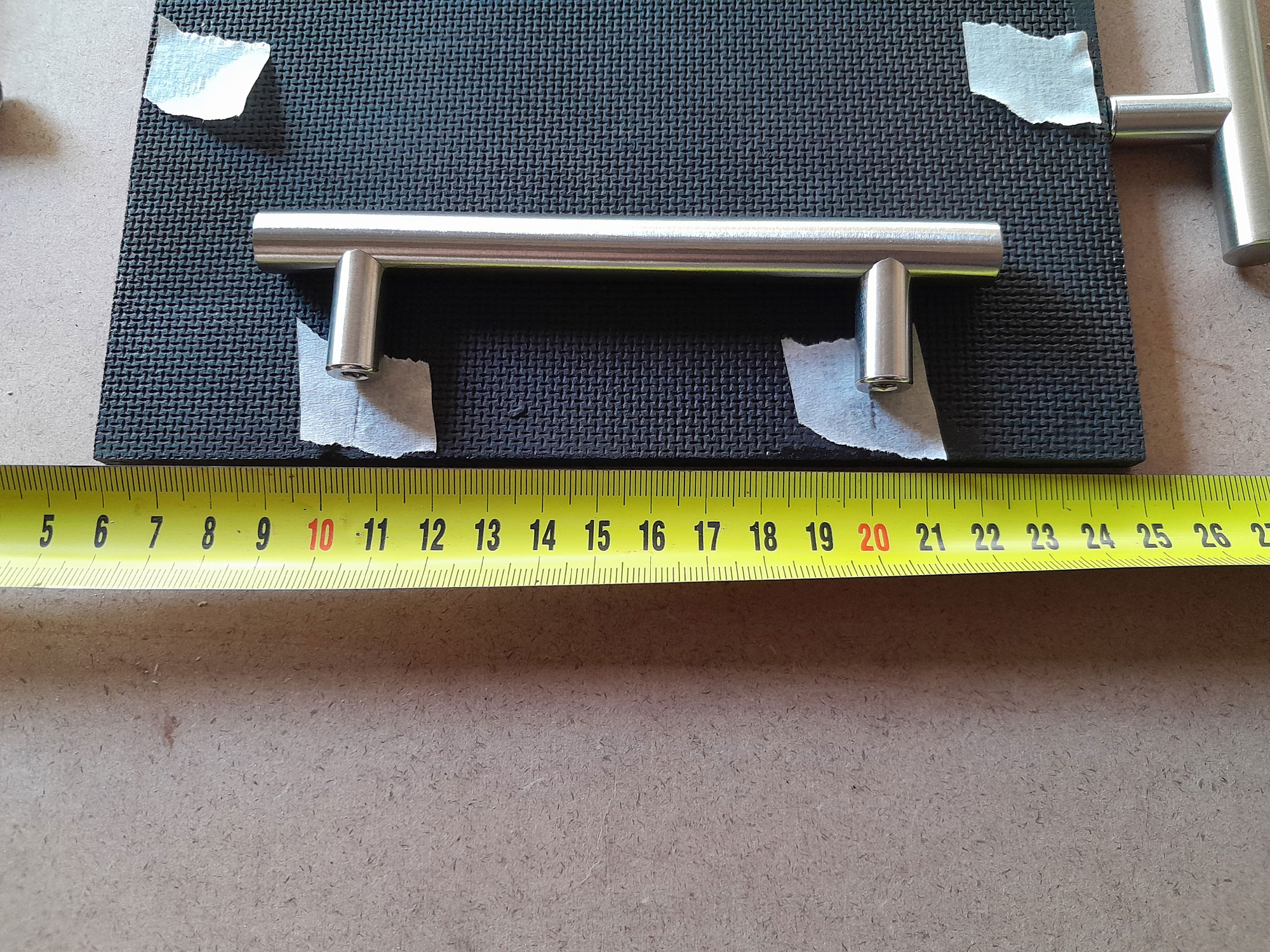
- Once satisfied, I drilled the holes.
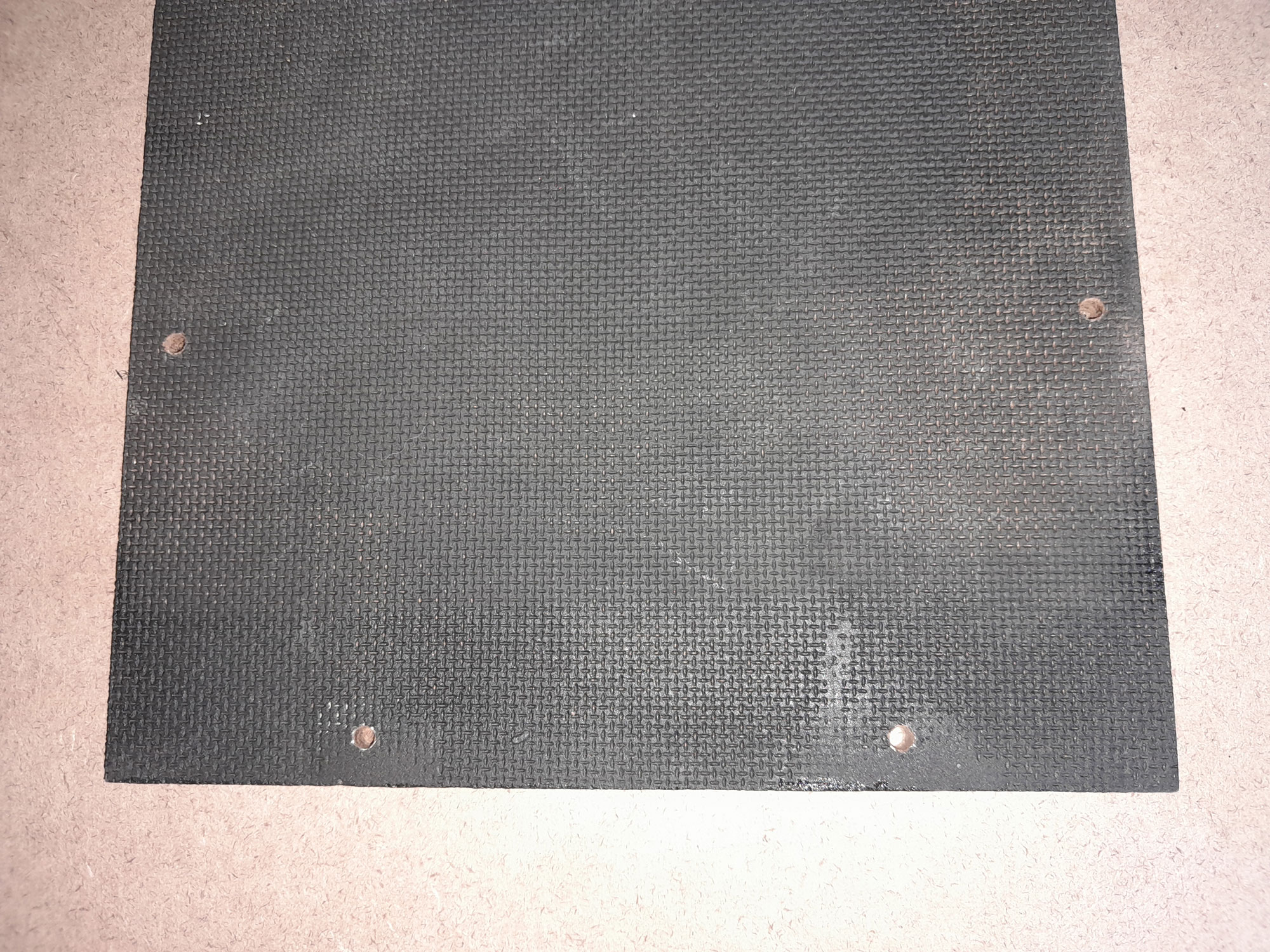
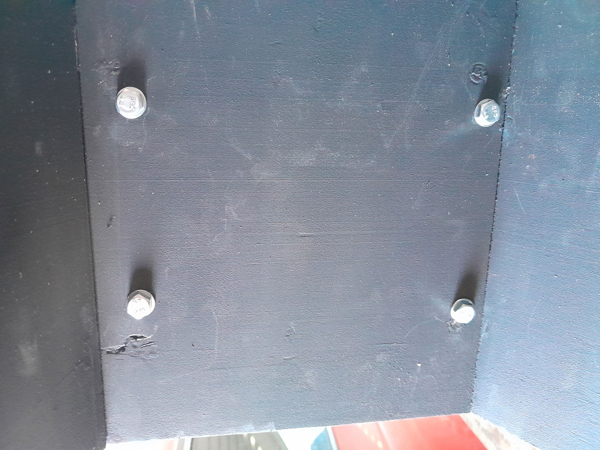
- All ready to go, and I added a 4mm brass flat washer to cushion each screw. In passing, the screws I used are shorter than the ones supplied with the handles as those supplied proved to be a little long. The important thing to remember is that the screw heads must not protrude more than the pads you will be using. If they do, you will mar the surface on which the tray is placed. If necessary, use CSK (countersunk) screws, without washers to secure the handles.
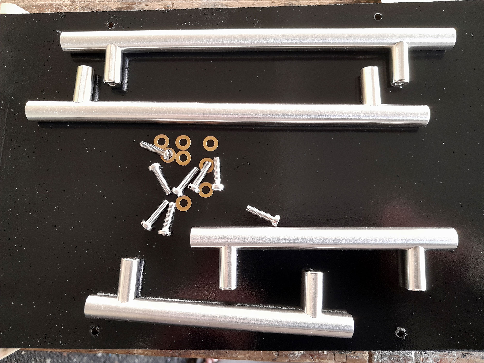
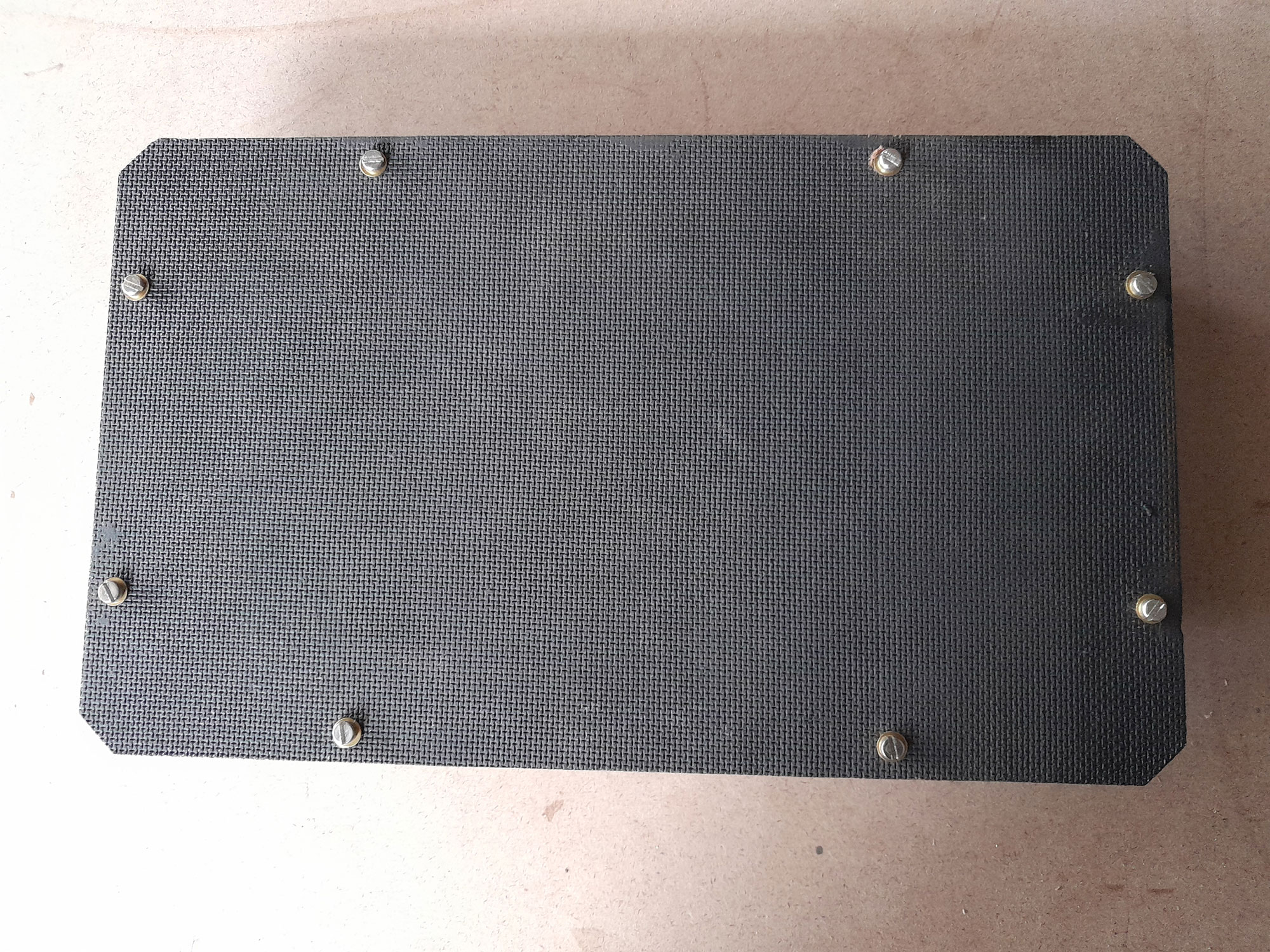
- At this stage, I decided to trim each corner at 45º as I had dropped the board and the one corner was slightly damaged so it occurred to me that trimming them would not only make damage less likely, but also make the corners less “sharp” – and trimming them does not reduce the carrying area of the tray at all. I touched up the cut edges using the same paint, applied in a puddle on some scrap wood, and using an ear bud to apply it.
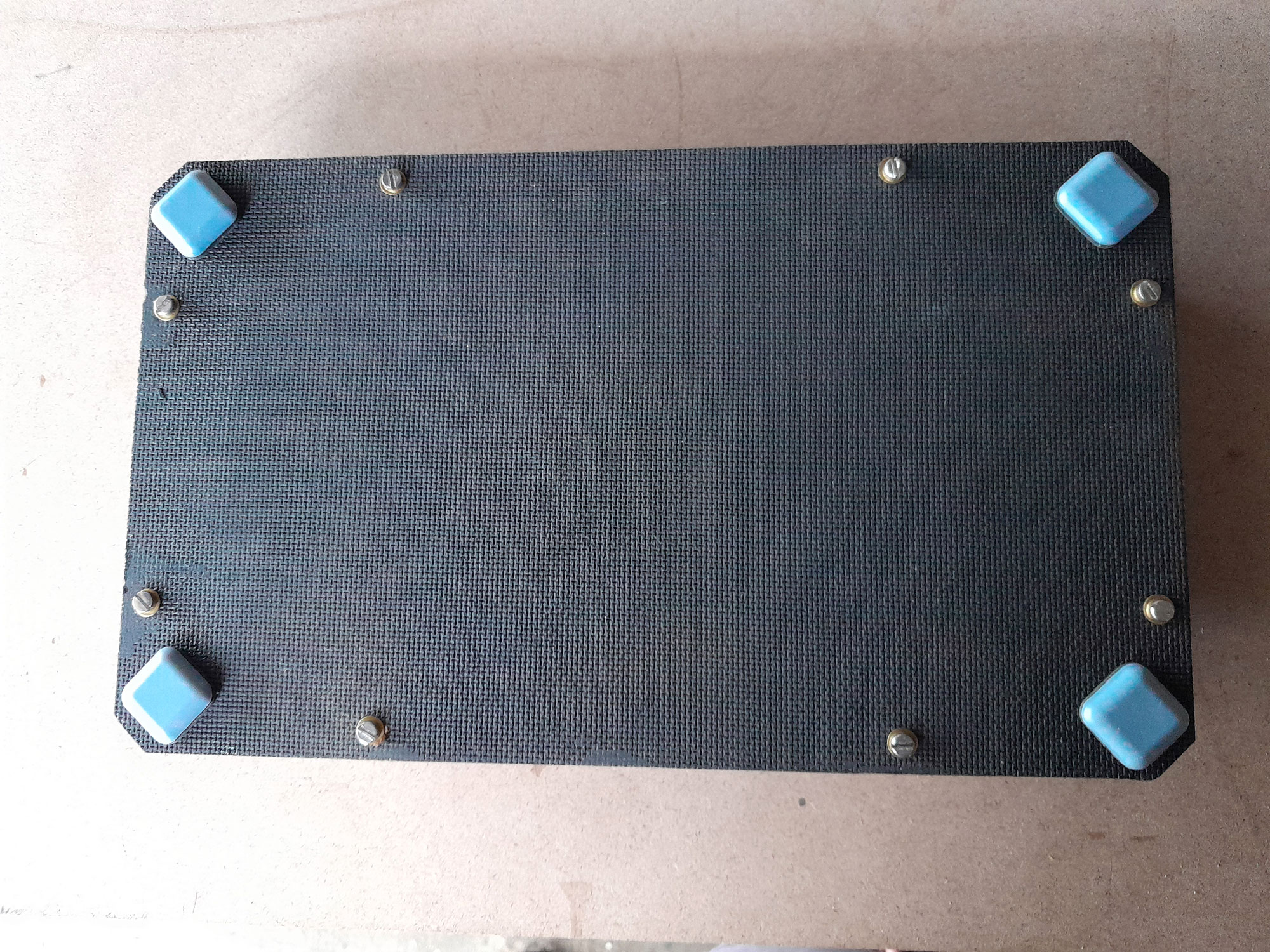
- I finished off by adding a slider pad on each corner as shown.
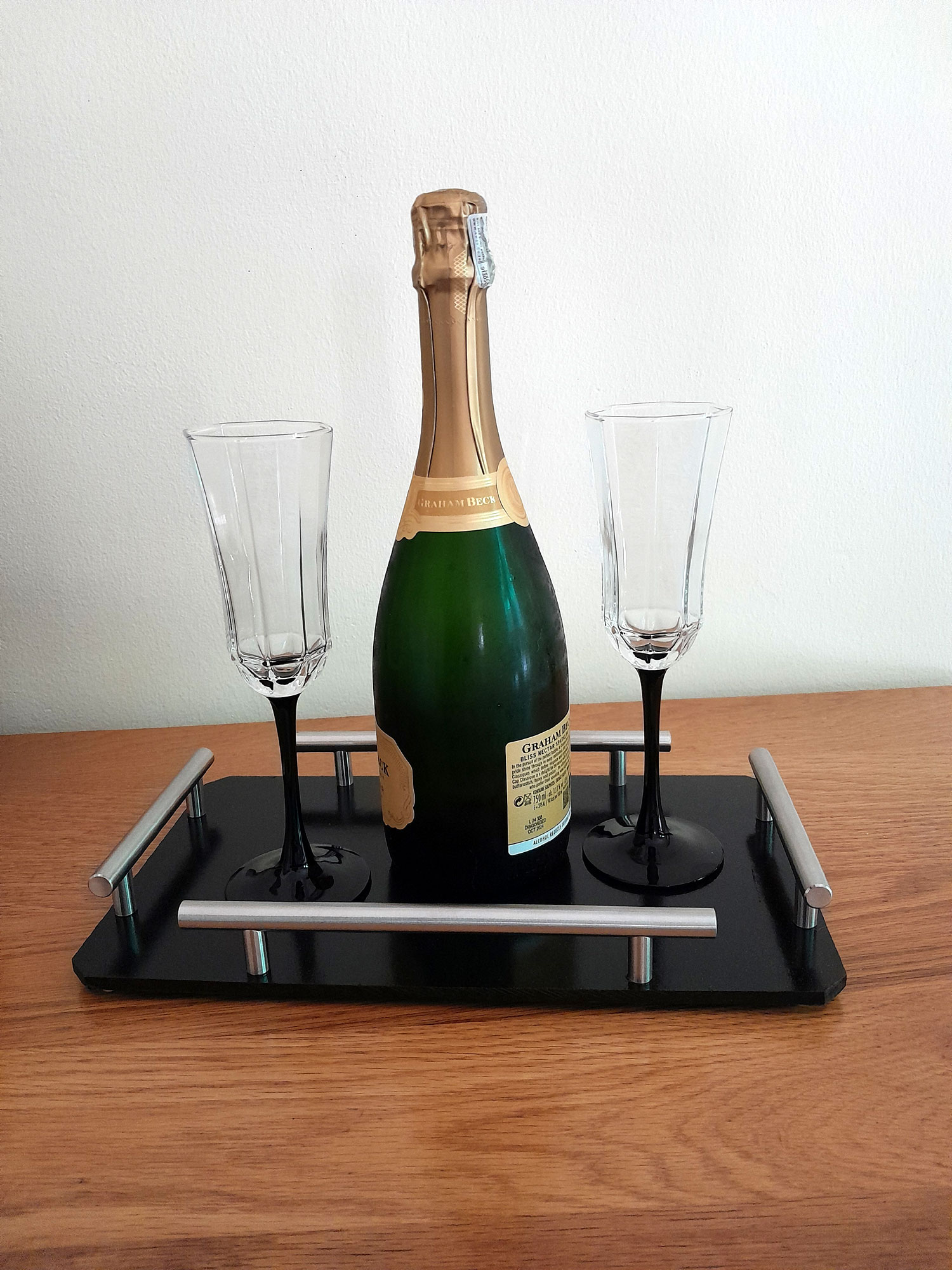
- And here we are, ready to provide much-needed sustenance to an eager recipient or three.
Panel:
These materials are available at Selected Mica Stores. To find your closest Mica and whether or not they stock the items required, please go to www.mica.co.za, find your store and call them. If your local Mica does not stock exactly what you need they will be able to order it for you or suggest an alternative product or a reputable source.
Project guide
TIME: 1 day or so
COST: R200
Skill: 1
Assistant: No
Tools required:
Jigsaw, drill/driver (cordless or mains)
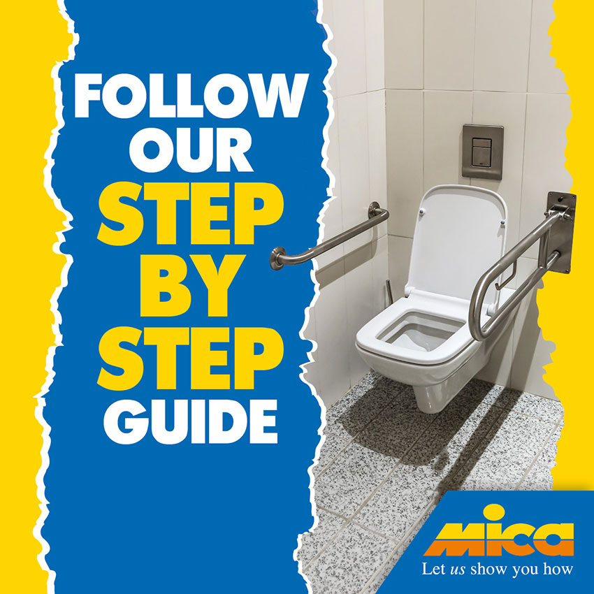
Are you sitting comfortably?
Using the loo is something we all do, and when young and supple, not difficult. But with age, certain medical procedures or infirmity can come challenges, particularly when getting to your feet again, so that that is when a pair of grab handles will make all the difference.
Just one caveat… these handles will be required to tolerate quite heavy loads so bear that in mind when selecting them… if one or both break free when being used, the user could be injured if they fall.
This is rather like fitting grab rails in the shower, but there are some differences in procedure.
And we’re off…
Materials:
- Two 304mm grab handles*, though if you have persons of very different heights in the house, then you might need an additional pair
*These handles are smooth, but they are also available with a cross-hatching pattern milled into them for enhanced grip.
Method:
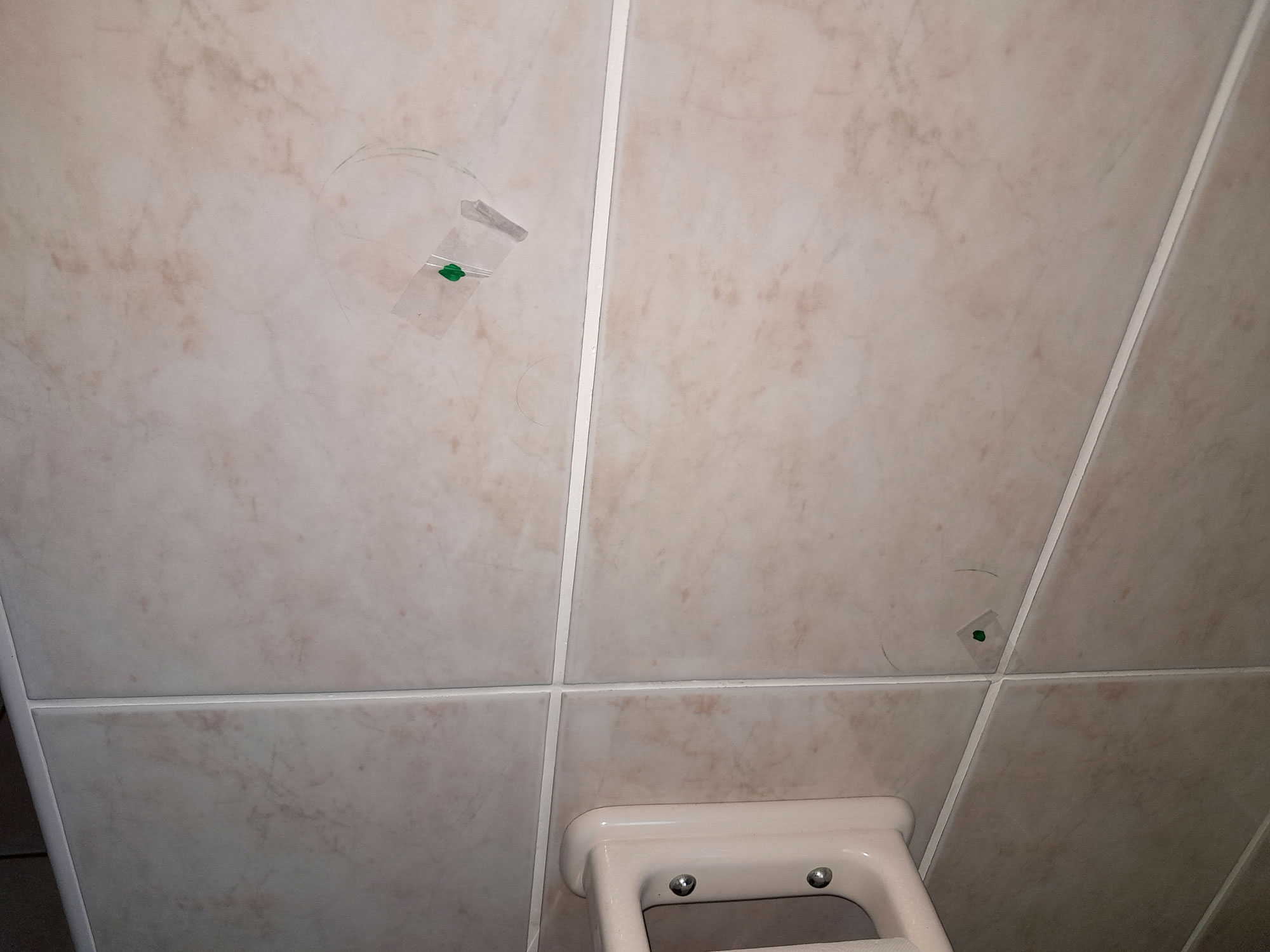
- The first step is to have the intended user or users plonk down on the toilet and holding the handles, decide where they would like them to be fitted – height, optimum angle, and distance ahead of the toilet. And mark the positions of the two attachment points on the tiles.
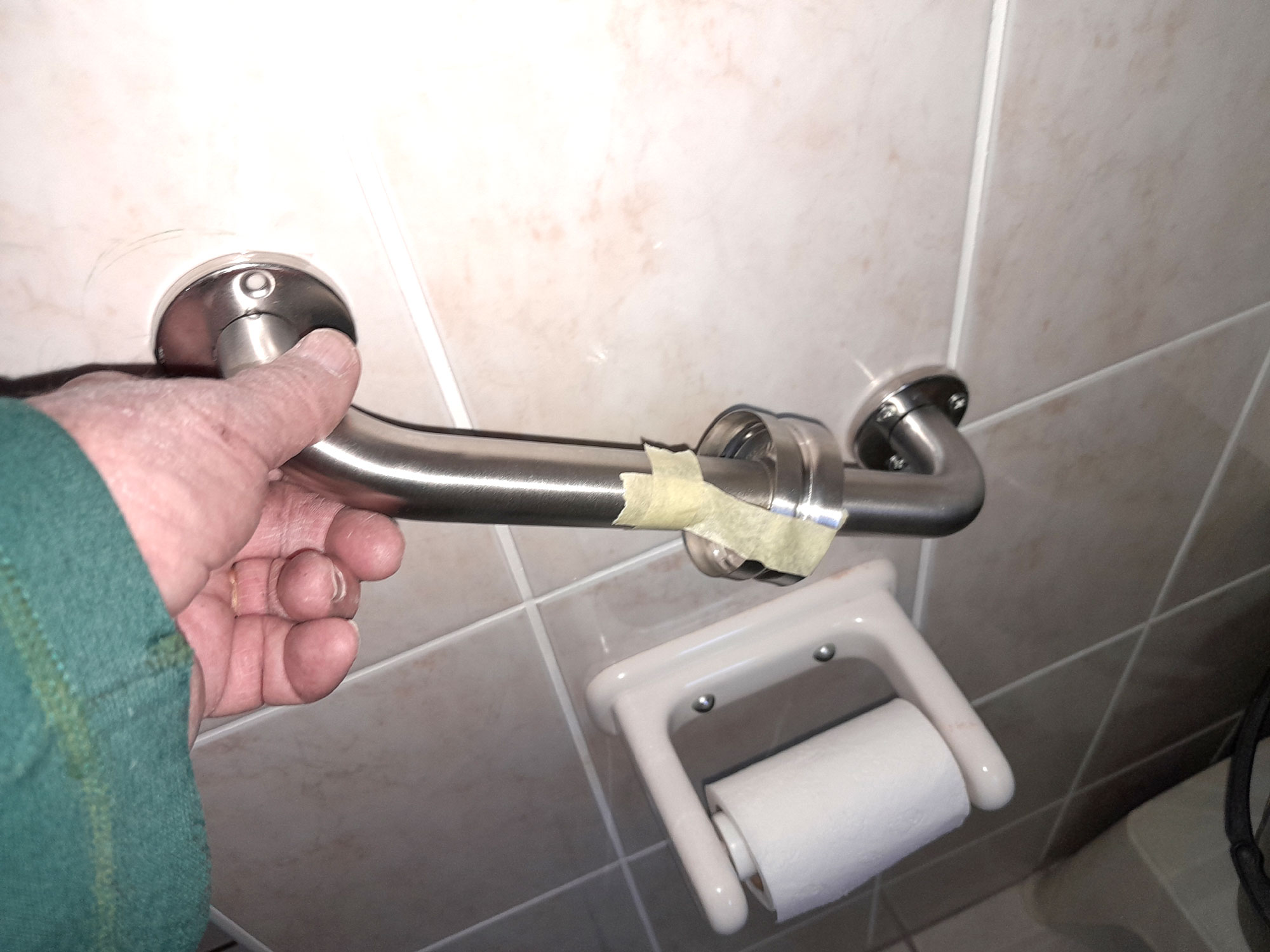
- Hold the handle in its chosen position and confirm its angle, height and position are what are desired – double-checking is always a good idea because if you get it wrong and you have to reposition the handles, you might say some naughty words. Note that as this handle had to be mounted on the wall of a shower cubicle, it could not be attached right up at the edge of the wall as this could cause cracking of the tile and brickwork substrate, so it is set back just 100mm or so.
- With the attachment flange removed from the rail (if it can be, but if not, no problem, simply hold the entire handle in position), mark the positions of the securing screw holes to be drilled…
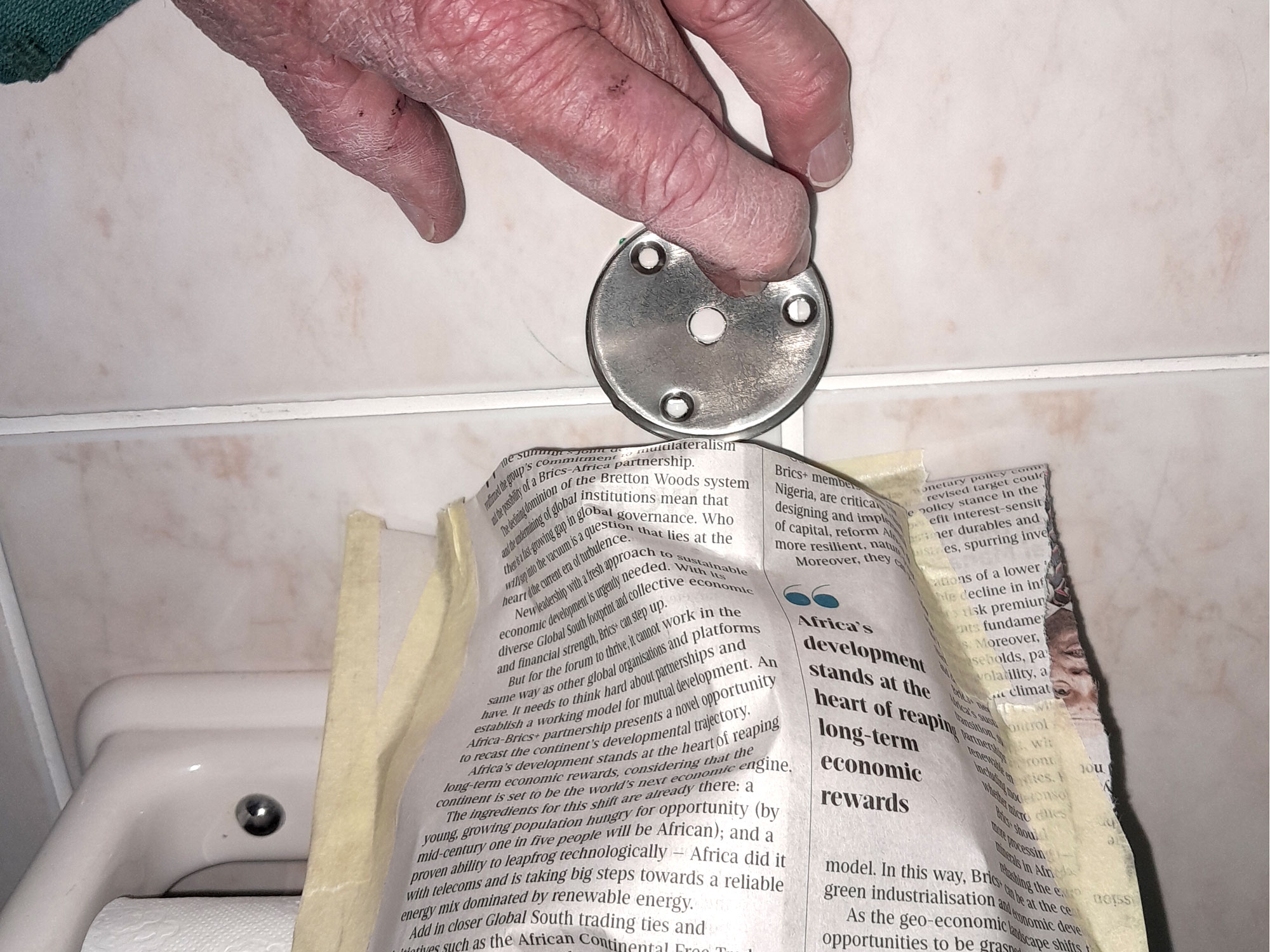
- Like so. Note that though the position and angle should be optimum, there is a little leeway, and here I have positioned the attachment flange holes so that at least two of them pass through the grouting and just the one through the tile itself. Note the use of the newspaper sack to catch debris from the drilling. I repeated the process for the lower flange.
- When drilling through tiles and masonry it can be a good idea to use a smaller bit to make the hole, and then use the correct size one to complete it – it allows you to achieve a more accurate drilling position. Most important, use the drilling mode when starting the holes, and switch to the hammer function only when you are through into the brickwork substrate; if you use the hammer action from the start, you could crack the tile.
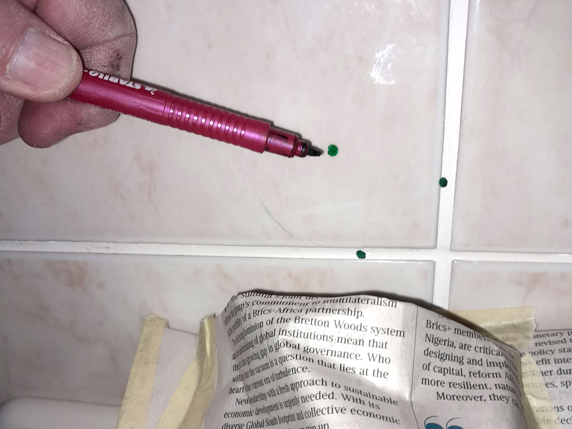
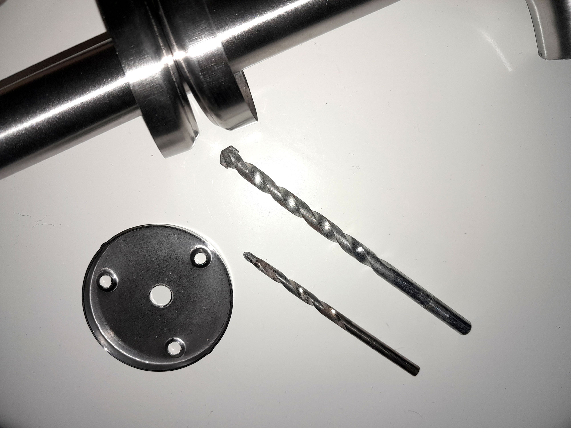
- The holes have been drilled and their depth checked with the small bit to ensure that the wall plug is fully seated. If not, drill the hole deeper. The same procedure was repeated with the lower attachment flange.
- And completed installation.
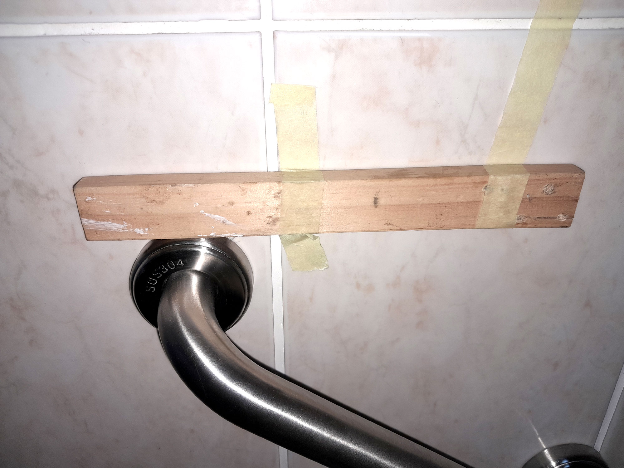
- Now the trick is to ensure that handle on the opposite wall is at exactly the same height and angle. I used a piece of scrap wood, taped to the wall dead level, as my marker.
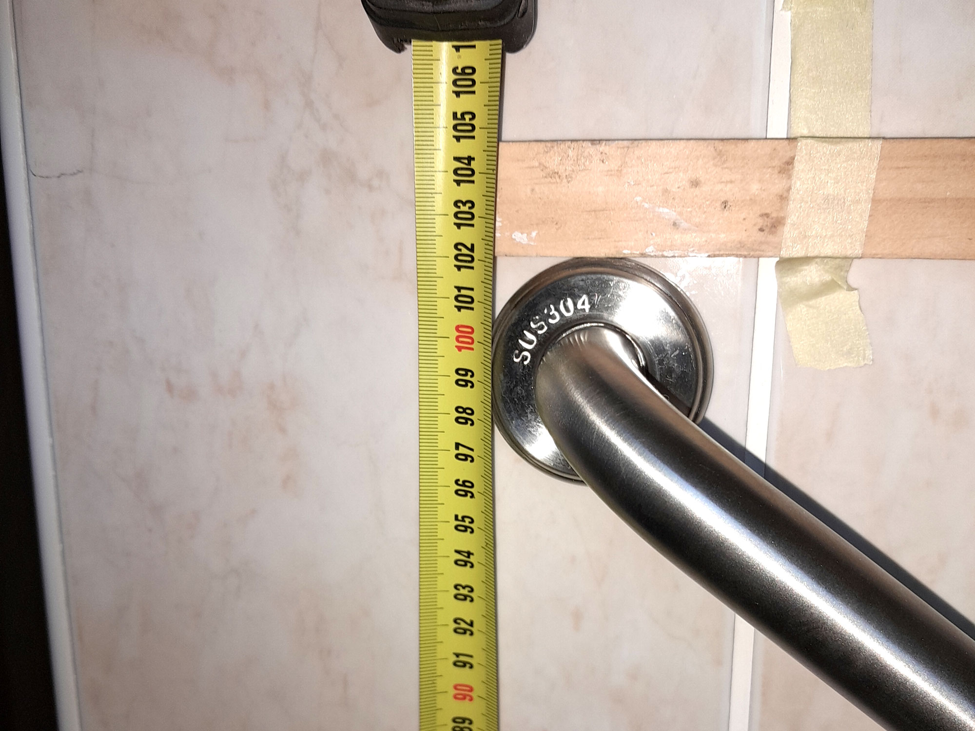
- Then it was easy to measure the height from the floor.
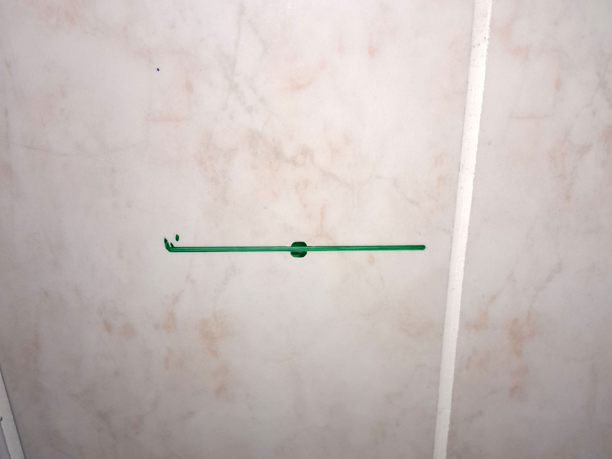
- I marked that height on the opposite wall, that below the window, with the top dead centre of the flange indicated by the dot on the horizontal line.
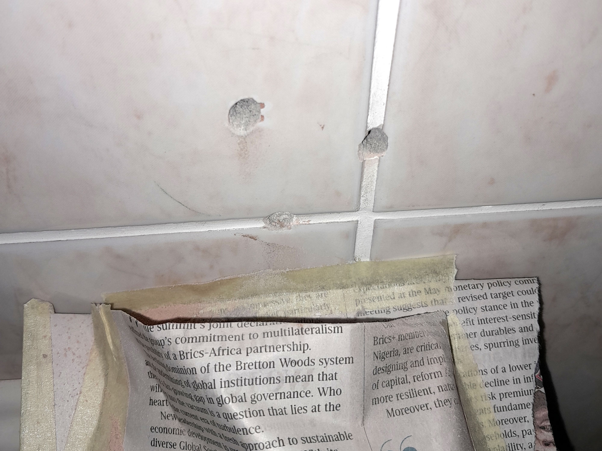
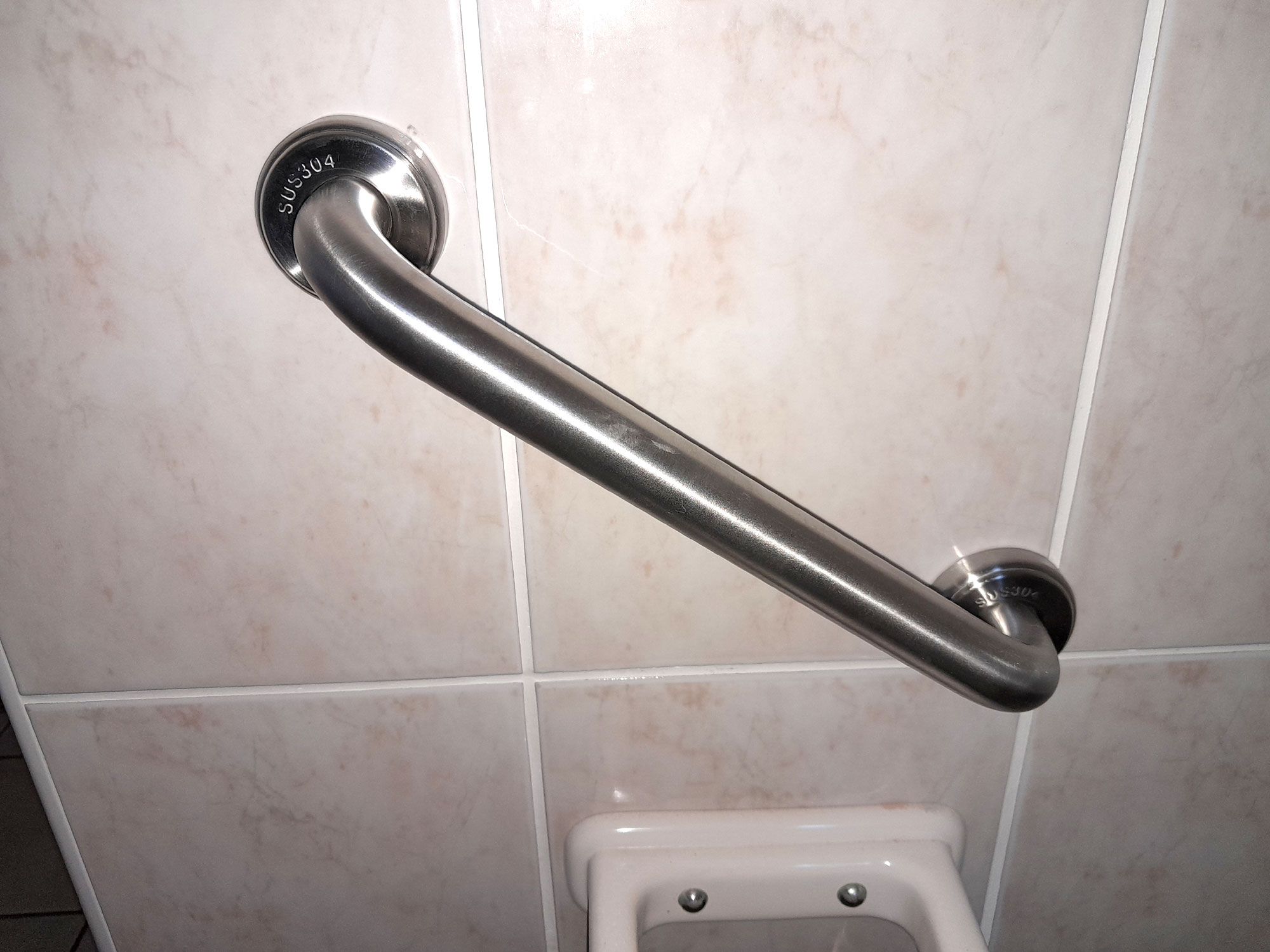
- I confirmed the angle and attached the second handle to the wall.
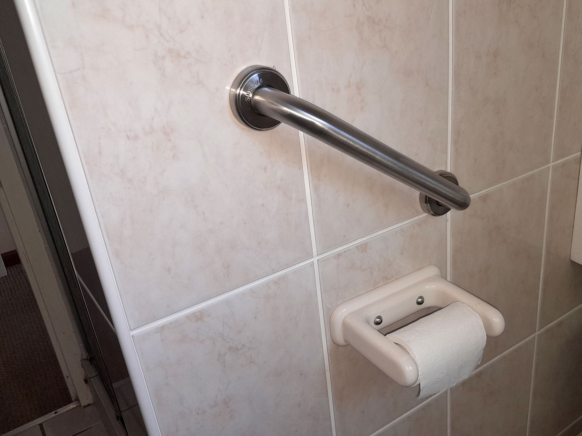
- It matches up perfectly with the left-hand handle mounted first.
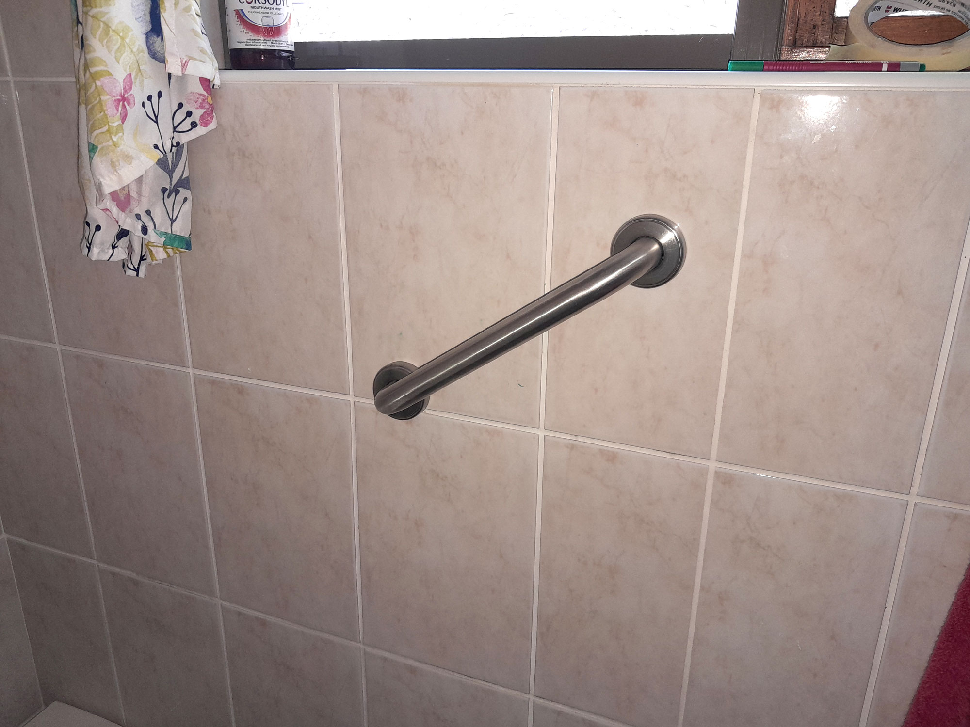
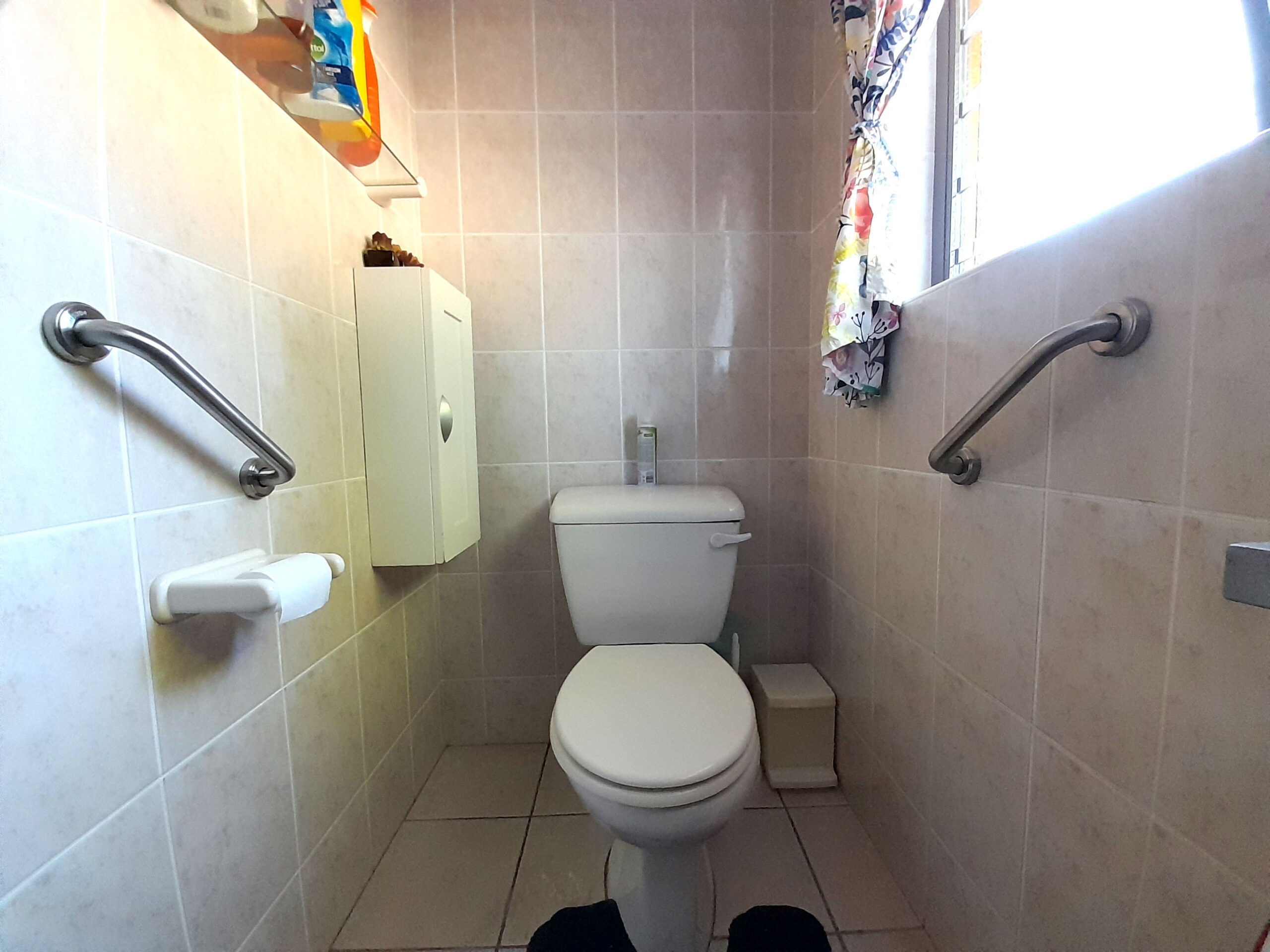
- And here is the completed task – both handles are at exactly the same height, angle and distance from the rear wall.
Panel:
These materials are available at Selected Mica Stores. To find your closest Mica and whether or not they stock the items required, please go to www.mica.co.za, find your store and call them. If your local Mica does not stock exactly what you need they will be able to order it for you or suggest an alternative product or a reputable source.
Project guide
- TIME: An hour or so, if that
- COST: This depends on the cost and length of the handles, and the number you buy. These were 304mm long, and range in cost from around R200 and upwards, but they are available in longer lengths – obviously at higher cost.
- Skill: 2
- Assistant: No
Tools required:
Cordless or mains drill/driver with hammer mode.

Meet the Wood-n-Book-n-Wine Rack
This multipurpose rack is essentially modular hexagonal that can be added to, if you wish with a third or even fourth hexagon, even on top. Construction is relatively simple, but you have to ensure that your measuring of both its sides and its angles are very precise.
But being multipurpose, it is literally a rack for all seasons.
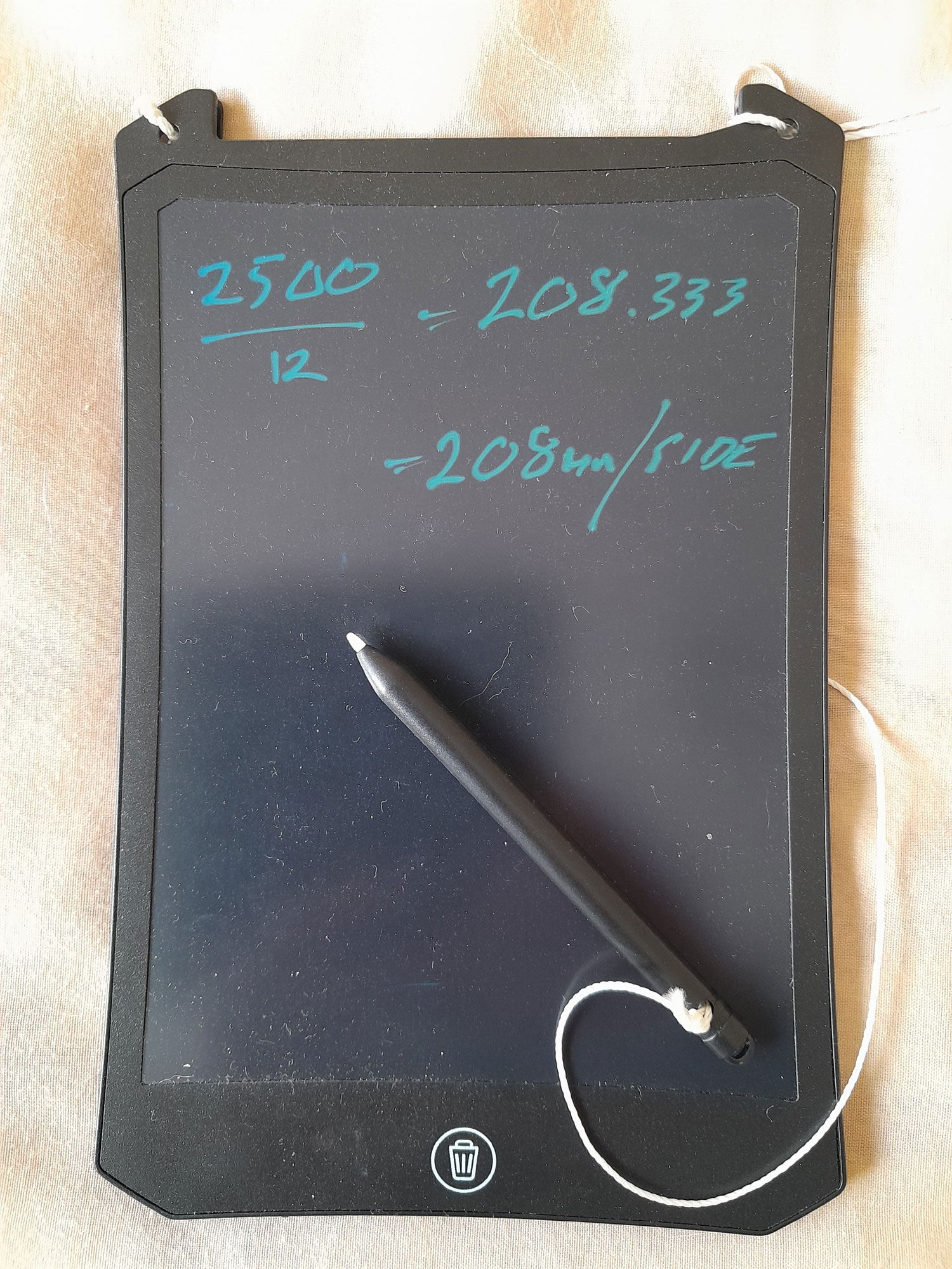
I sized each hexagonal to make the best possible use of the (optional) aluminium flat bars. Each is sold in 2500 lengths, and as each would be cut in half to make up 1250 each, and then in turn bent to make six sides, each side of the hexagon would be 208mm.
I also made up a tray to fit across the top of the unit when it is used as a book rack/side table, and two bookshelves, to fit across the hexagons, as shown.
You do not need to include the bars, but I did in order to strengthen each hexagonal part of the unit as it would be taking quite a strain when the rack is used to store wood during winter.
The total height of the completed unit is 480mm, by 730mm long and by 22mm deep, with feet being 292mm; the feet not only stabilise the unit, but also serve to provide clearance between the back of the unit and a wall. In passing if you add a third hexagon on the top, then you might consider lengthening the feet to ensure stability.
Let’s get started…
Materials:
- Main units:
- SA pine: two 1800mm lengths of 22×222 cut into 12 lengths of 210mm with both ends bevelled at 30º (naturally, if you want a deep or shallower unit then you would select timber of the appropriate dimensions. Likewise if you wish to make a large unit, then you need to take that into account when purchasing the length/s of timber
- One 600mm offcut of 22x96mm – for the feet
- Two 22x222mm sides, bevelled at 30º – these are cut from the leftover 22x222mm wood
- Wood glue
- Twenty 19mm pan head screws (optional – used only if aluminium straps added)
- Four 70mm 6mmØ bolts (may need to be trimmed by 5mm or so)
- Four 6mmØ dome nuts
- Four 40mm wood screws – to attach the sides to the top
- *Aluminium flat strip: Two 2500mm lengths of 20×1.5mm
- Finish of your choice. I used blackboard paint.
- Tray – 222x358mm:
- Base – 6mm ply, cut to fit between the side stays attached to the top of each hexagon
- Sides – 9x44mm cover strip ripped to approximately 9x20mm
- 20mm panel pins
- Aluminium handles – two of your choice, plus securing screws
- Shelves – 222x315mm:
- Two pieces of 3mm (or 6mm) ply or tempered hardboard cut to fit as shown. (I used 3mm hardboard but reinforced it with 3mm play offcuts, as both were handy, and as the saying goes… waste not, want not…)
*The aluminium straps are optional, but I used them to strengthen the structure.
Method:
- I find this LED writing pad very useful for various calculations, designs and so on. You can save you calculations, and then erase them when you wish to.
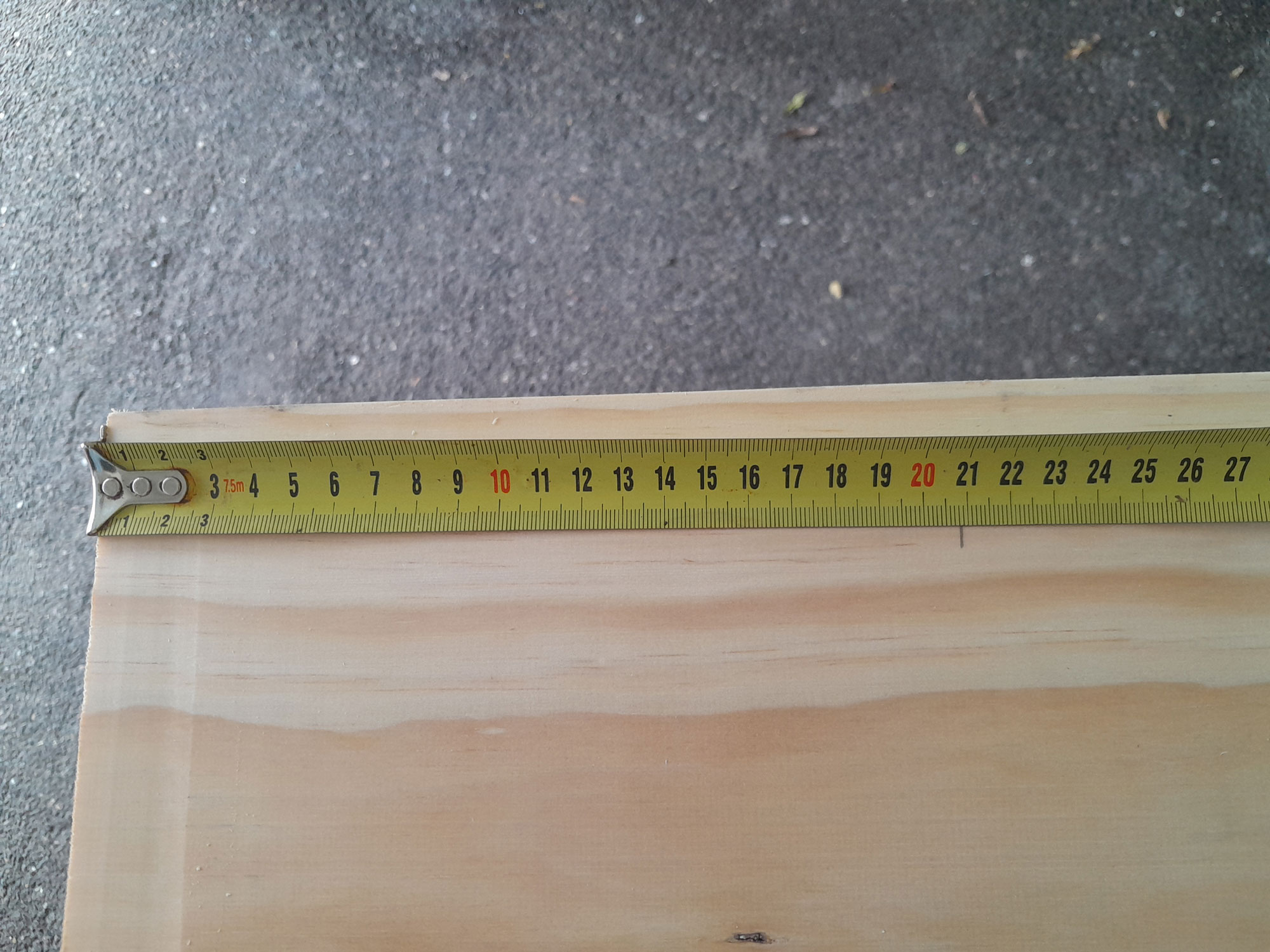
- First mark off your sides – each section of the hexagon is 210mm on the top and approximately 187mm on the shorter bottom edge, as each cut is made at a 30º angle.
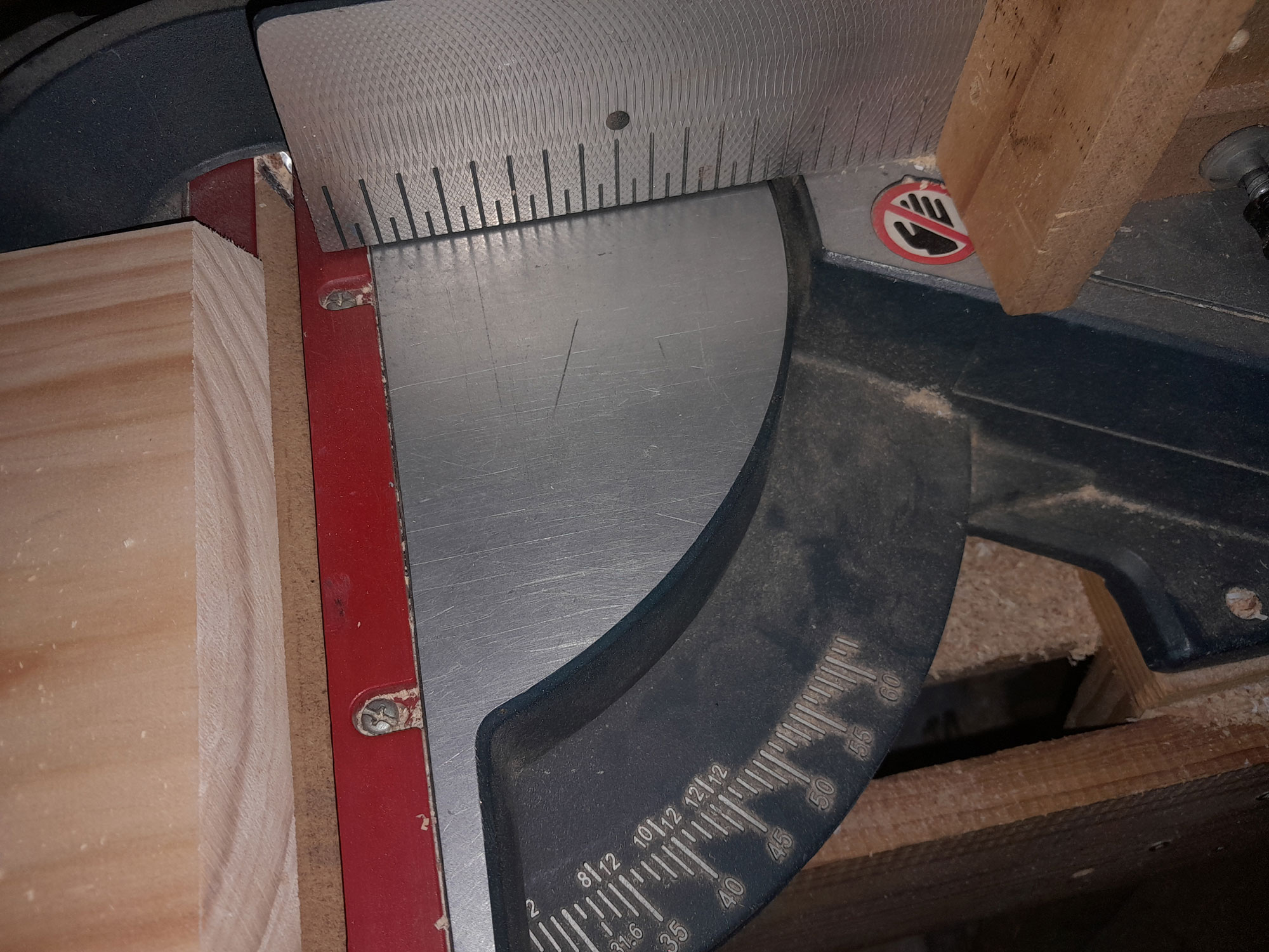
- With your mitre saw set to 30º, check that the blade will be on the cut line.
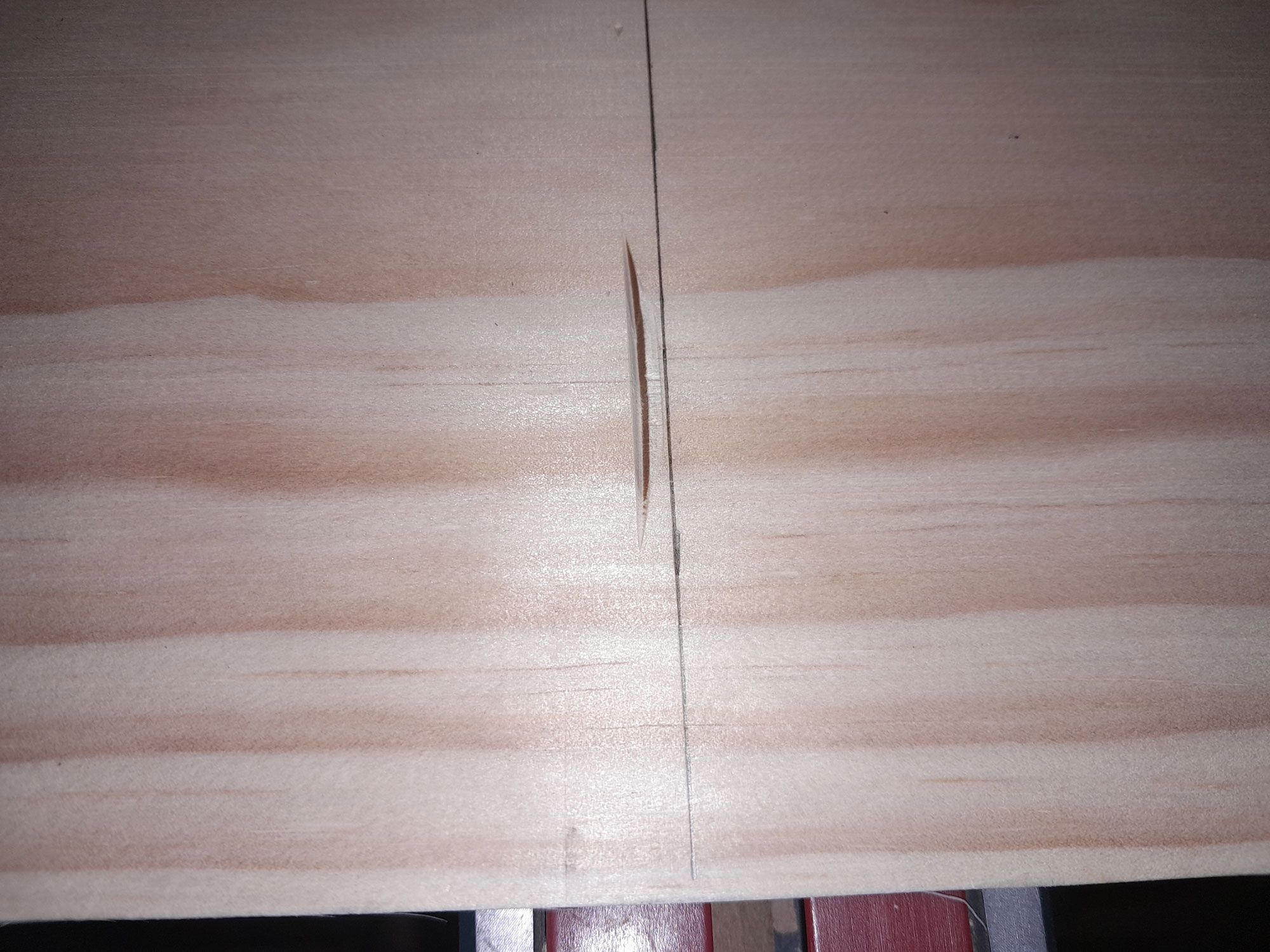
- This shows one bevelled end, cut at 30º.
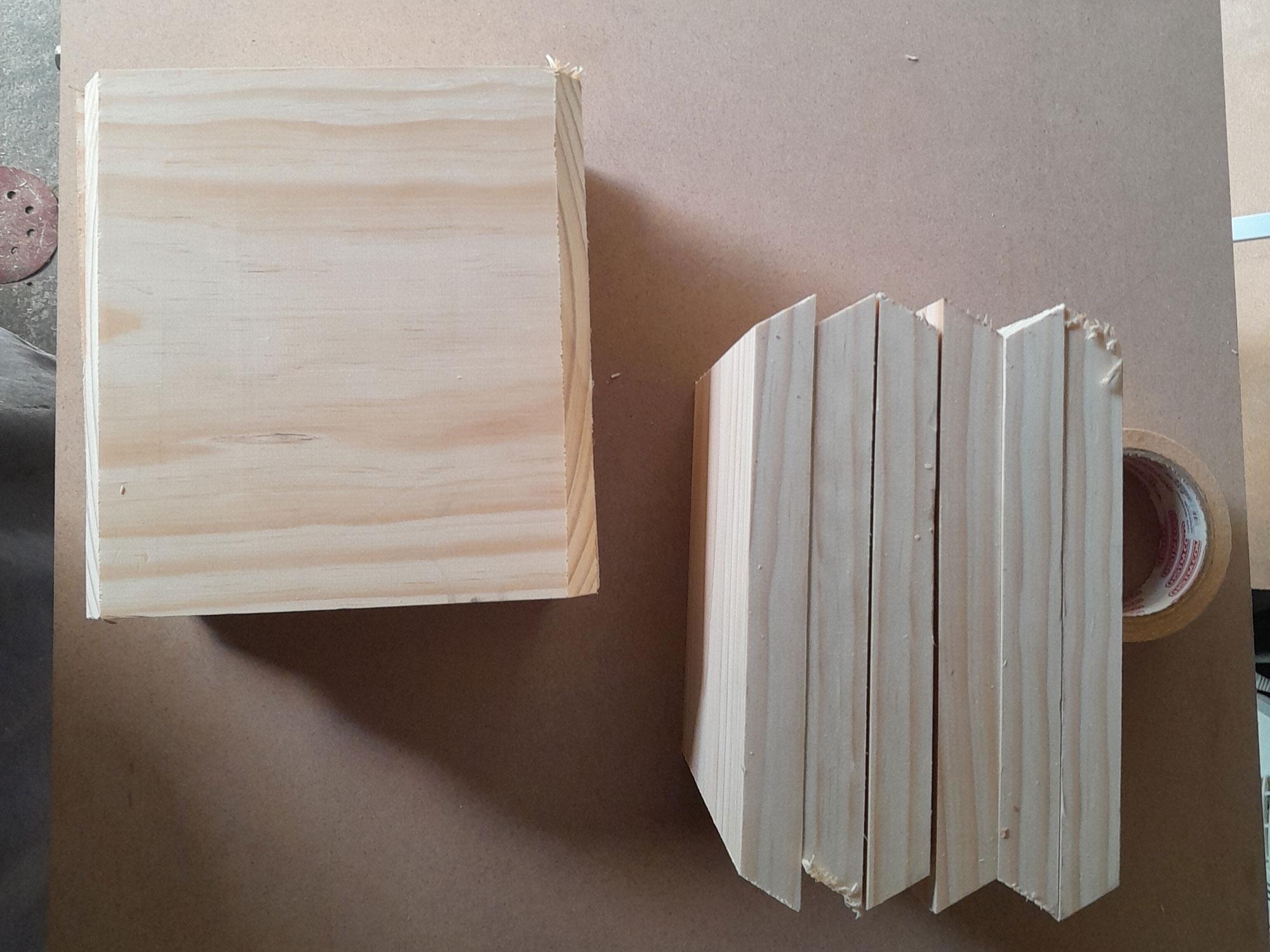
- And here are the 12 that have been cut. Each is exactly 210mm on what will be its longer, outer edge.
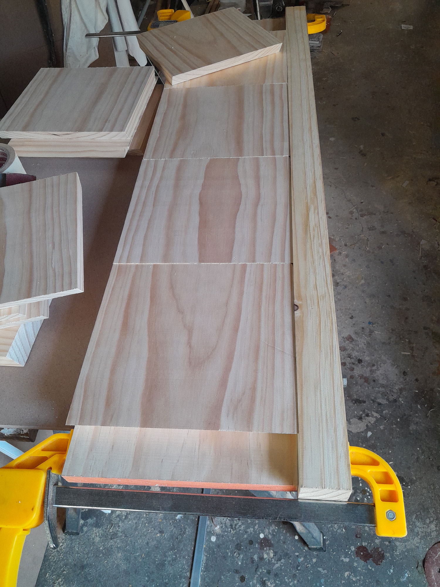
- I laid them out, using a length of straight wood on one side to ensure each segment would be absolutely aligned with its neighbours.
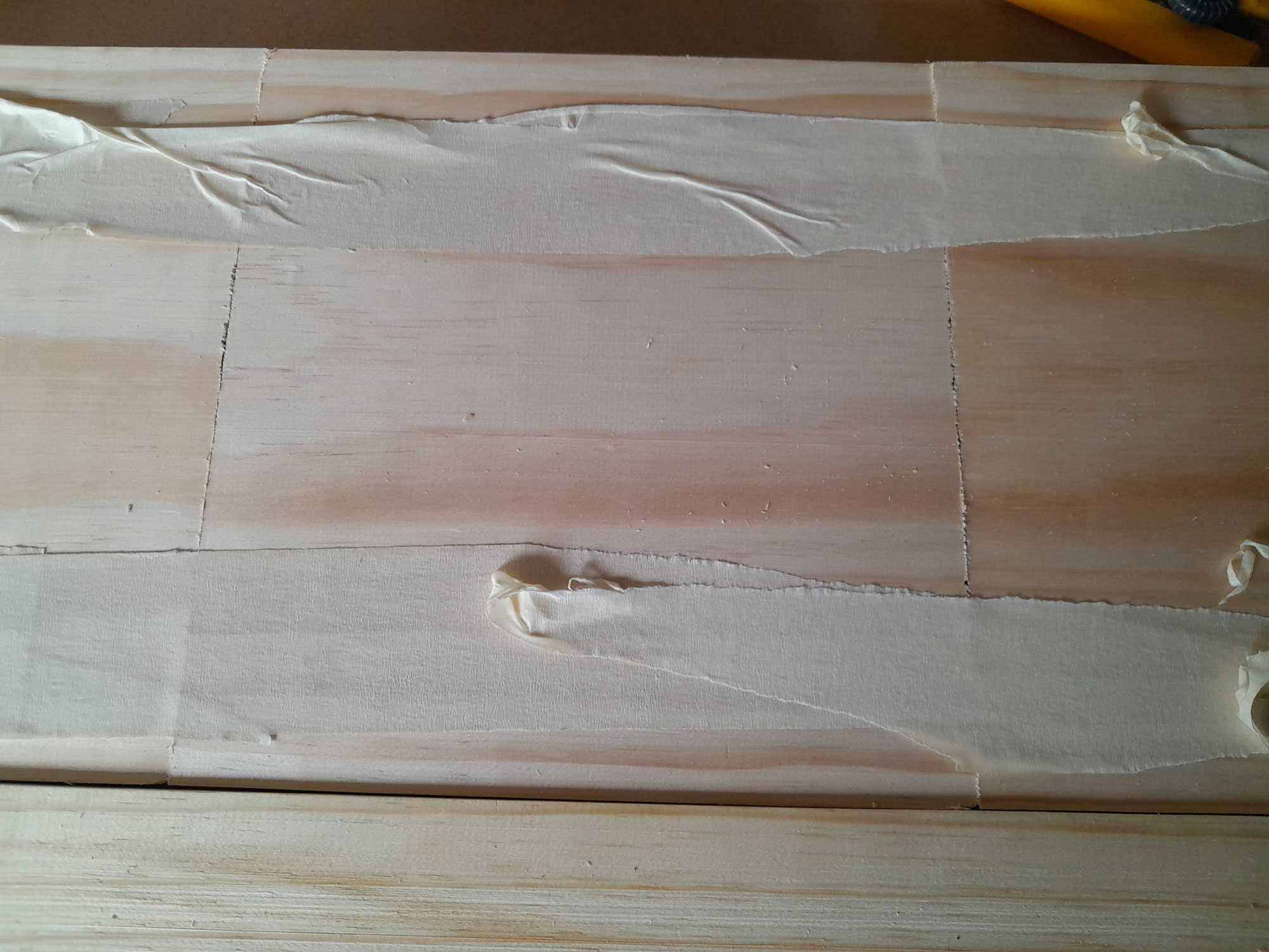
- I used wide masking tape to hold the segments together; in retrospect, luggage tape might have been a better option as it is stronger.
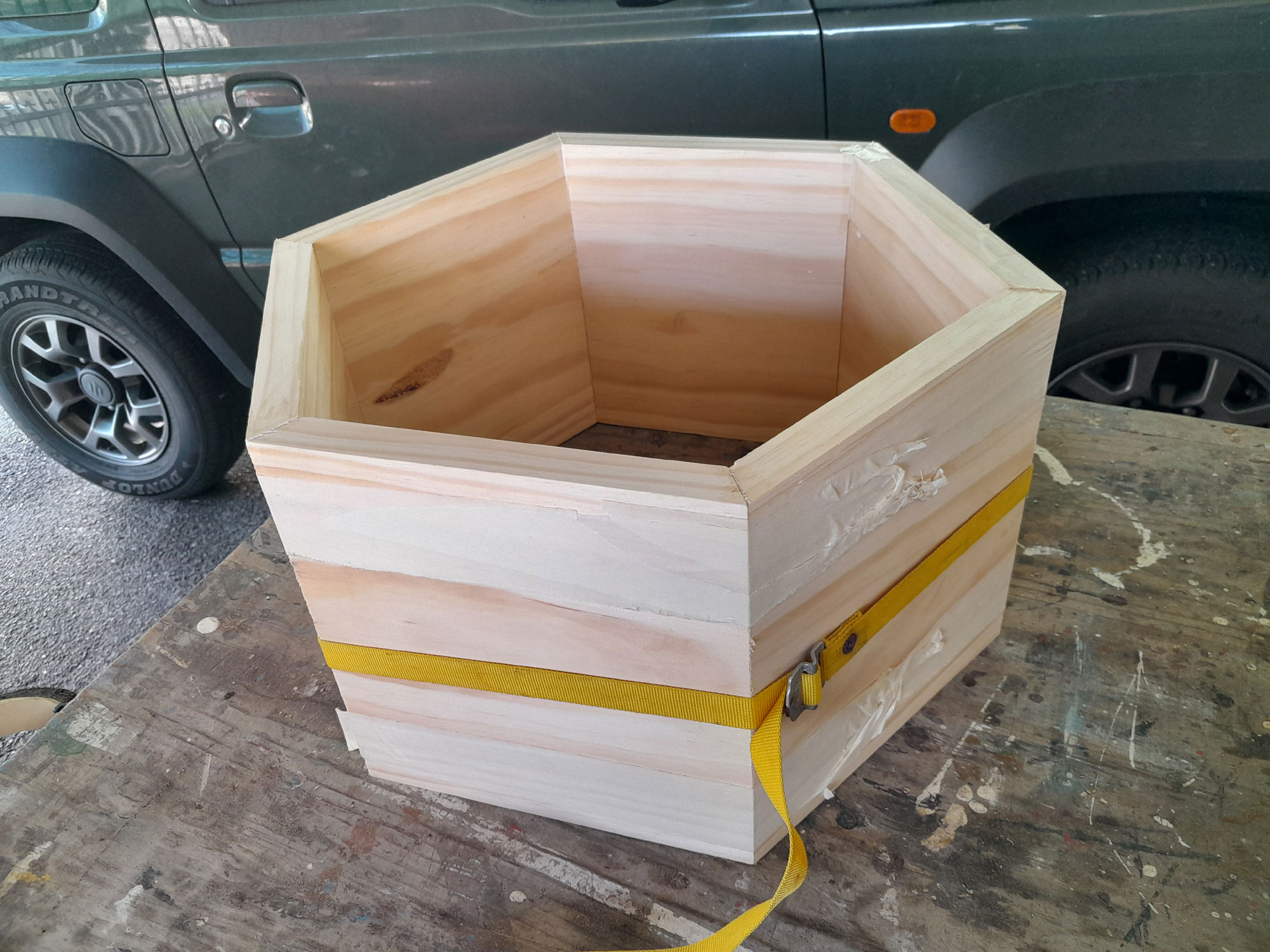
- Then I flipped them over on to their back and I applied glue to each segment meeting surface, and then carefully rolled the segments up, rather like a tank track, with some tape to hold them together. Then I secured them firmly with a luggage strap to hold them firmly together while the glue cured.
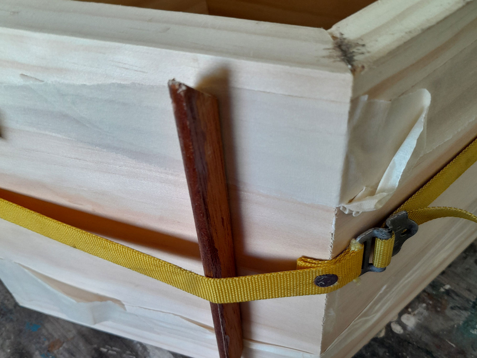
- To tighten the strap as much as possible, I pushed offcuts under the straps as shown. I also measured across the hexagon to ensure it was all correctly aligned. I assembled the second hexagon in the same manner.
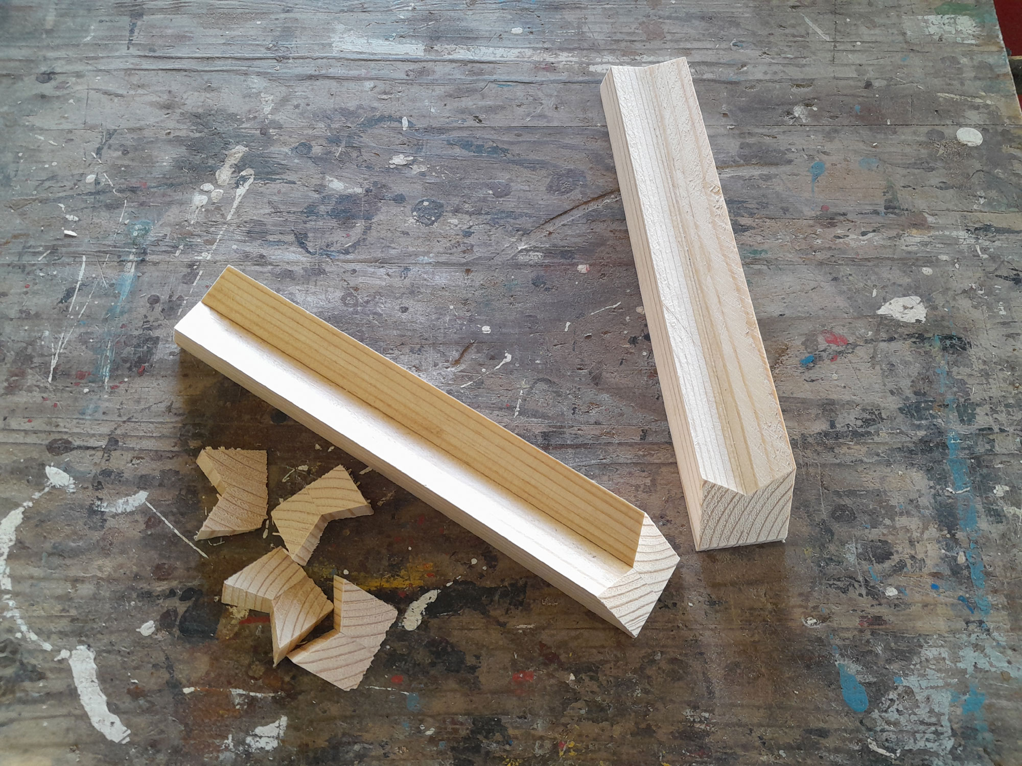
- Now for the feet… I marked off the centre of the 22x96x600mm offcut, cut it in half and ripped it down each length at a 30º angle.
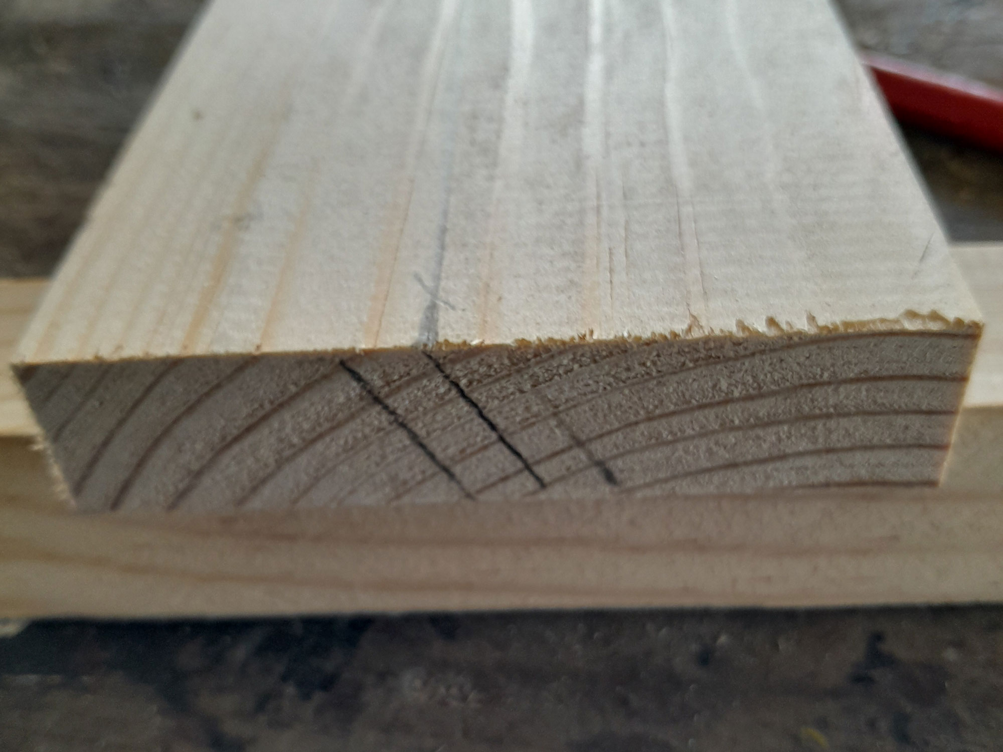
- Then I glued the pieces together as shown here and clamped them while the glue cured.
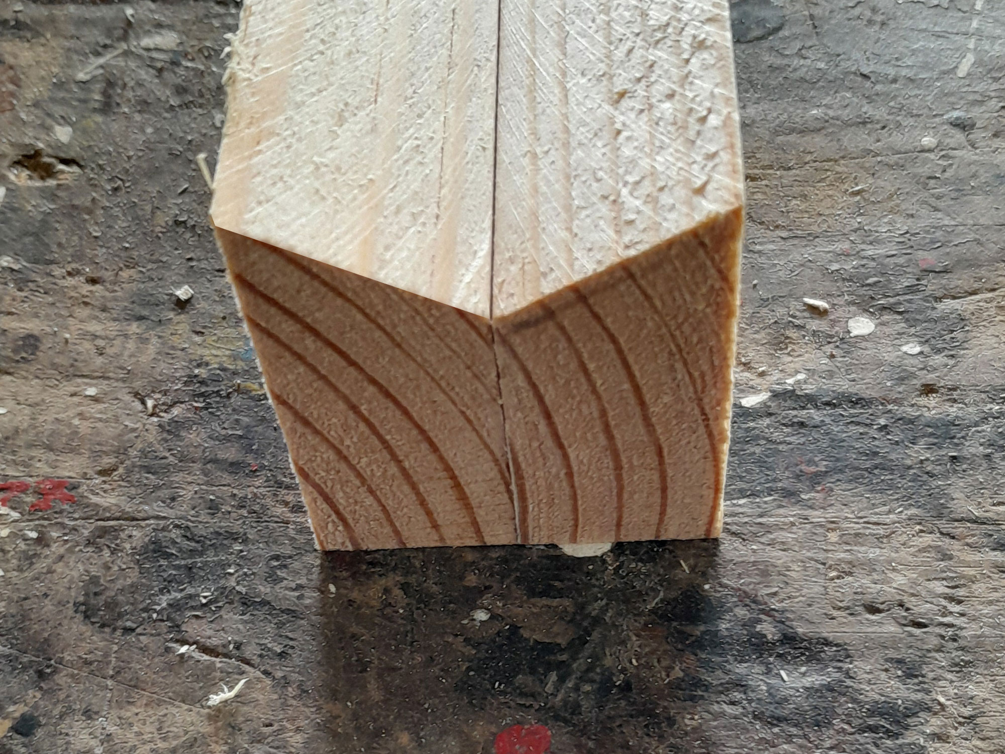
- The “V” of each foot needs to meet exactly as shown here.
- I bevelled each end at 30º, to match the rest of the angles, leaving a flat end of about 8mm on each end so that there would be no sharp edges to snag on a carpet.
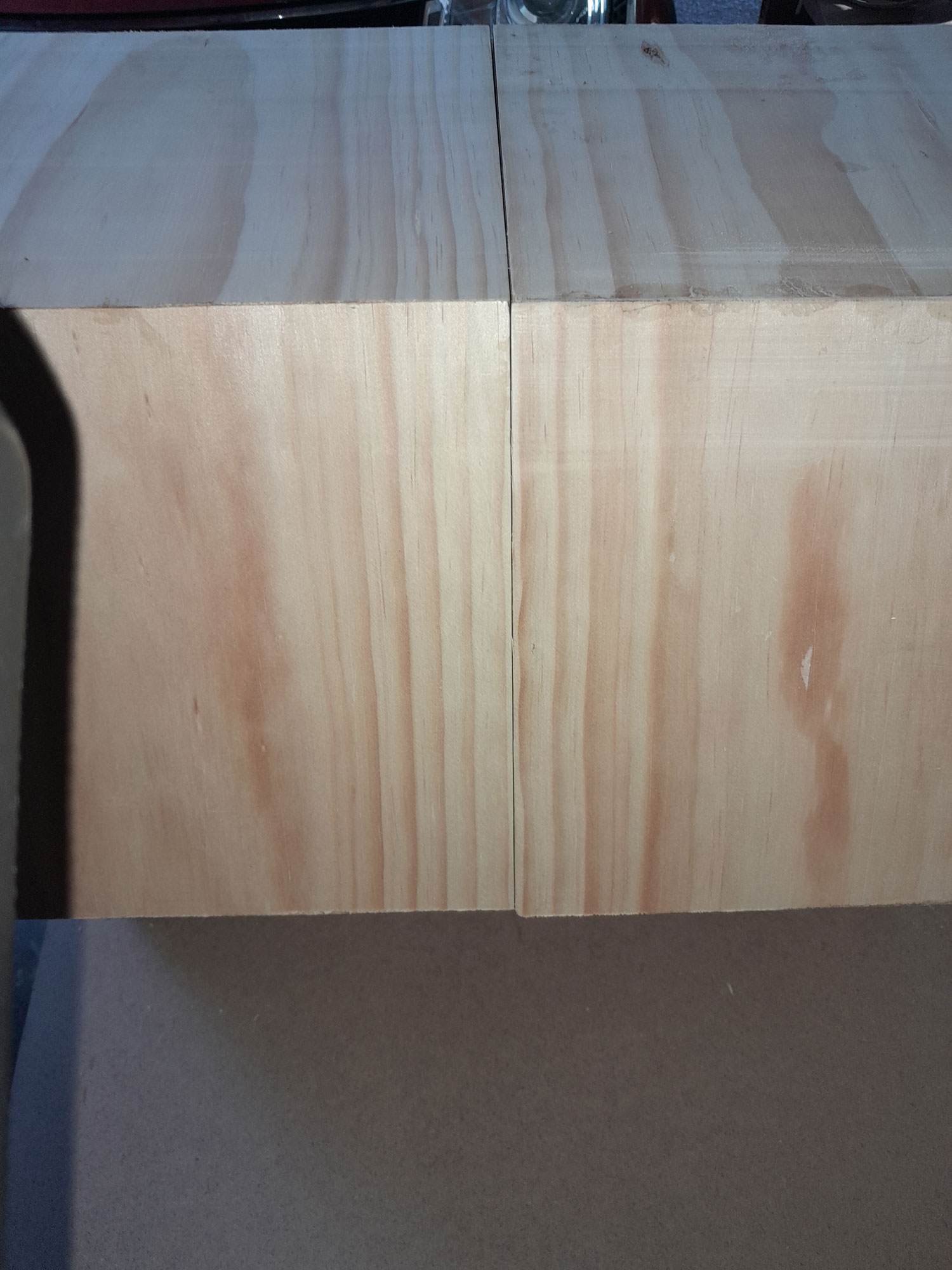
- By now the glue has cured on the two hexagons, so I was able to check that they were both a match. There was a slight difference of about 1mm along one facet, but other than that, they worked out well.
- I used a flat strapping bar, with its predrilled holes, as my template to align the four 6mm boots that would hold the two hexagon sections together. Then I drilled the four holes, from the outside.
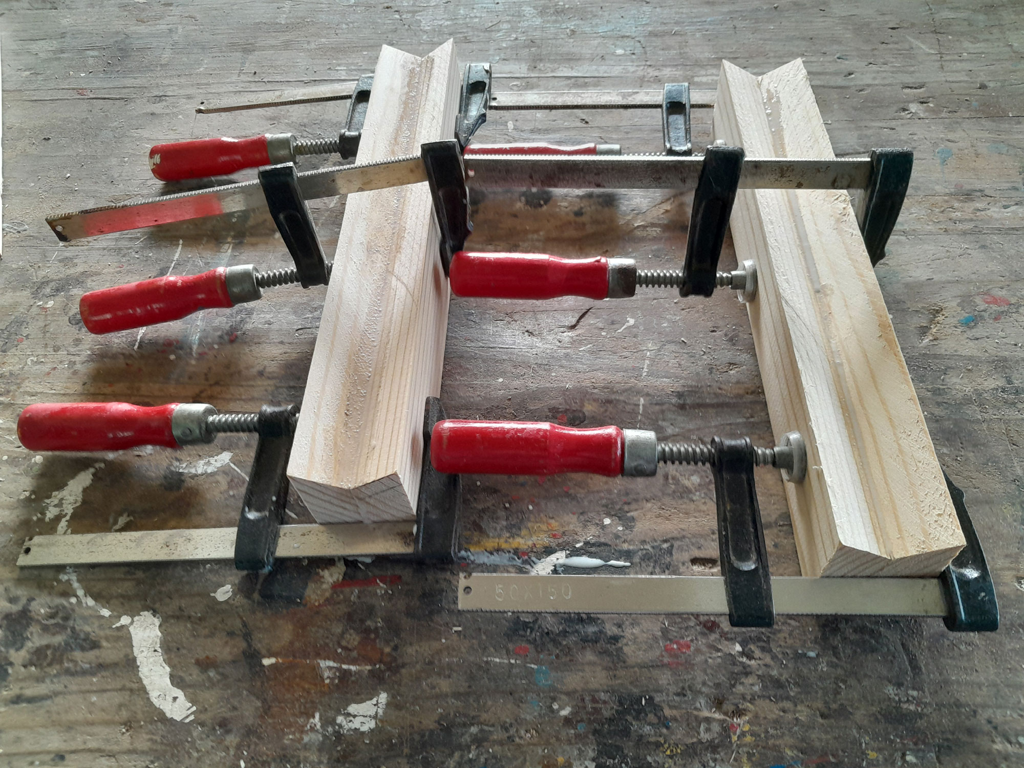
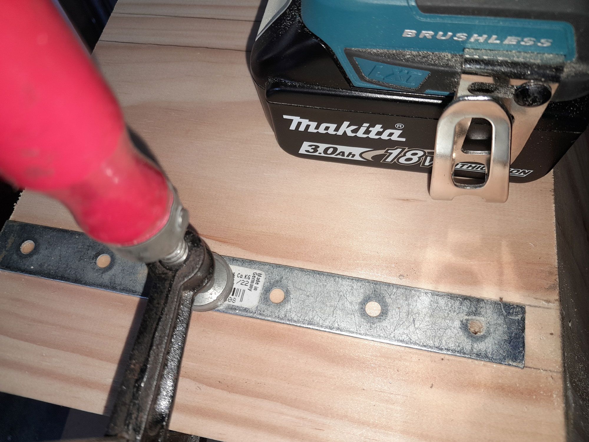
- Then I clamped both hexagons together, ensuring they were perfectly aligned and drilled through the holes already drilled, from the inside. So I now had four exactly matching holes for the bolts.
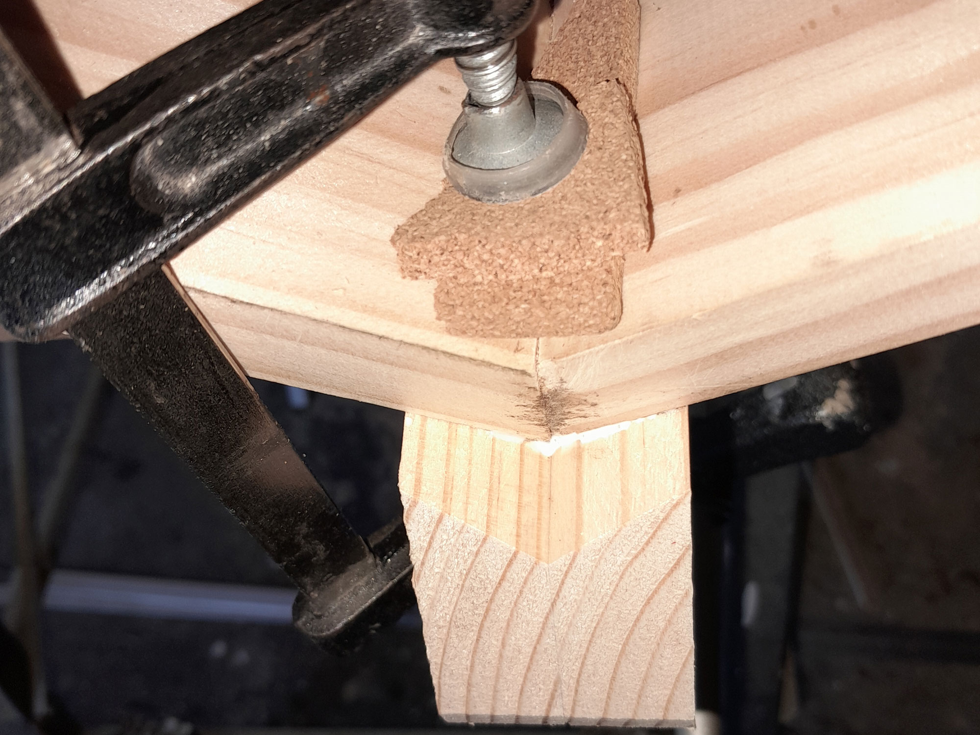
- My next step was to secure the feet to each hexagon, centring them and using some scrap cork left over from an earlier project as cushions, so the inner edges of the hexagons would not be indented by the clamp heads.
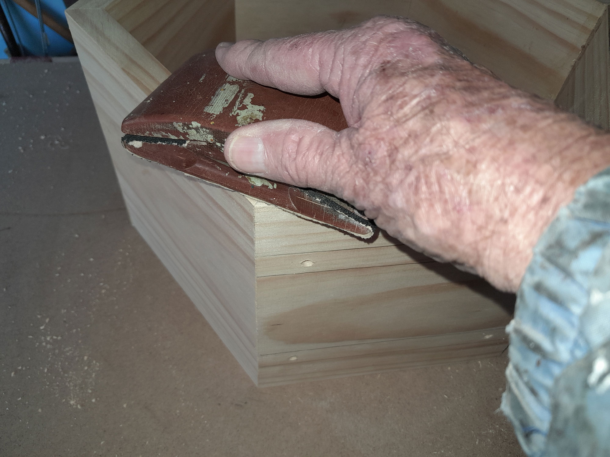
- Then I sanded off each join…
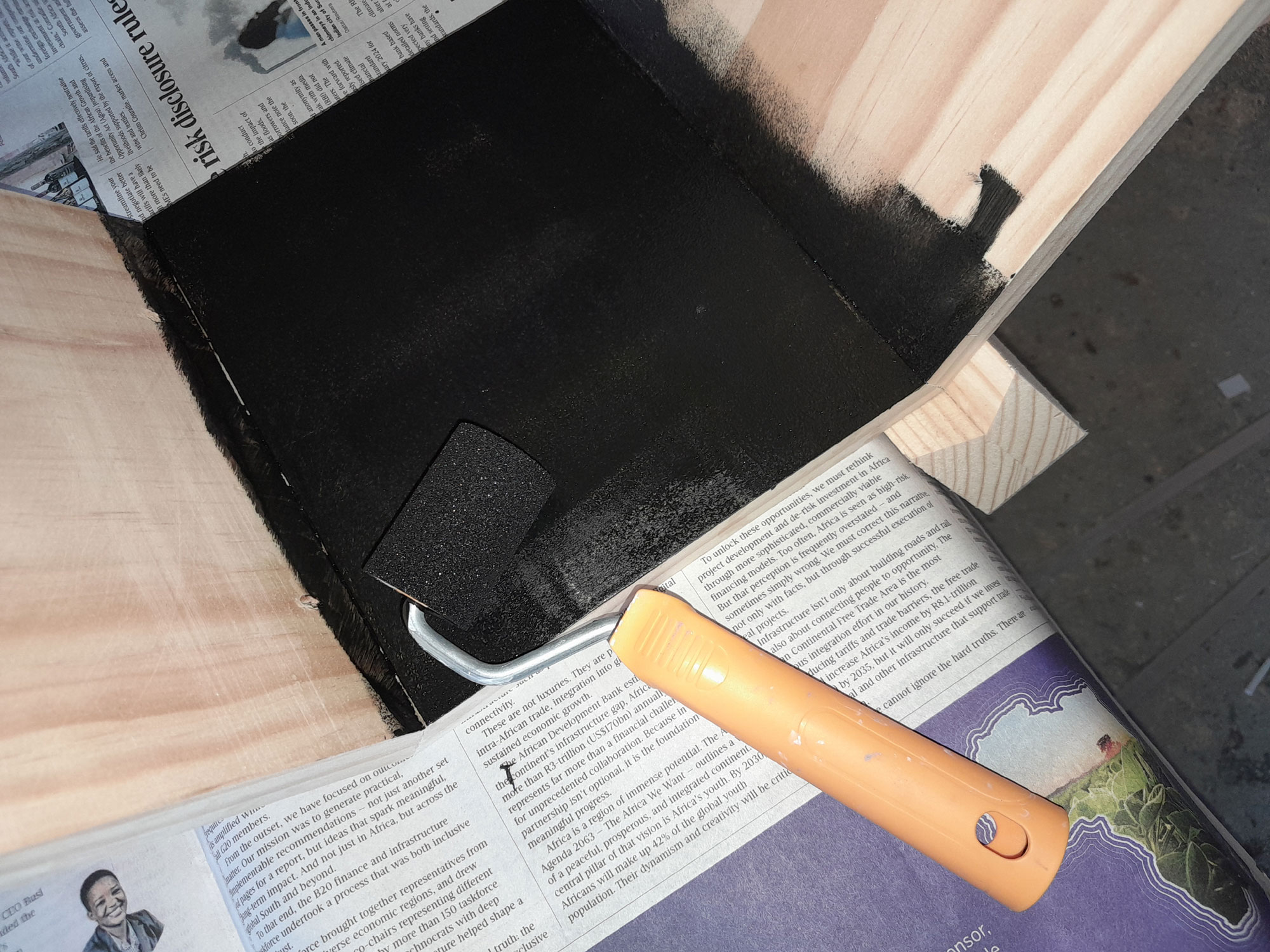
- And then I painted the inner surfaces of the hexagons.
- Followed by the outer surfaces. You can paint afterwards, but unless you are painting over the straps as well, you will need to mask them off. I found this to be much simpler, with just a little touch-up here and there where the paint might have been scuffed.


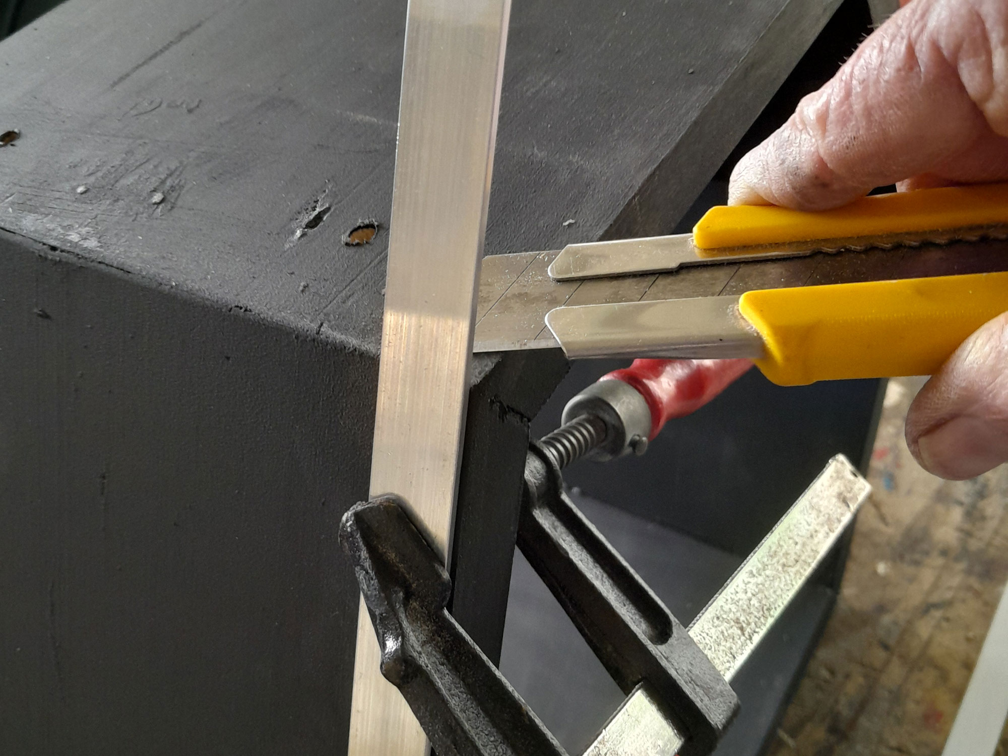
- I decided how far from the edge each strap would be placed – namely 44mm (a short length of 22x44mm wood is a useful gauge), clamped one end firmly against the first segment – that being the one to which the feet were attached – and used a utility knife to very accurately mark the position the bend would be made.
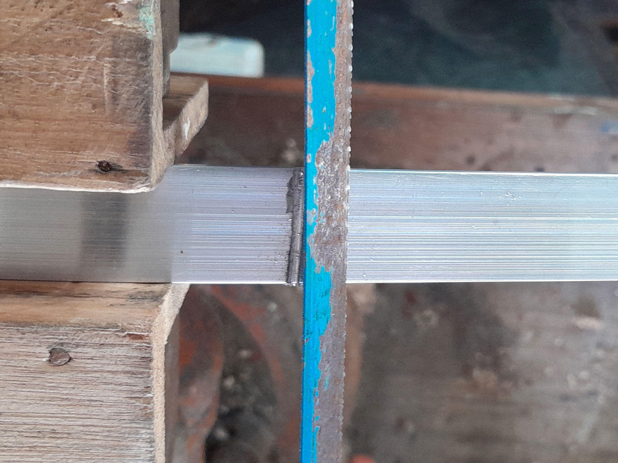
- Then I lightly scored along the mark made with the knife with a hacksaw… just a fraction of a millimetre to make the bend easier, but without impairing its strength.
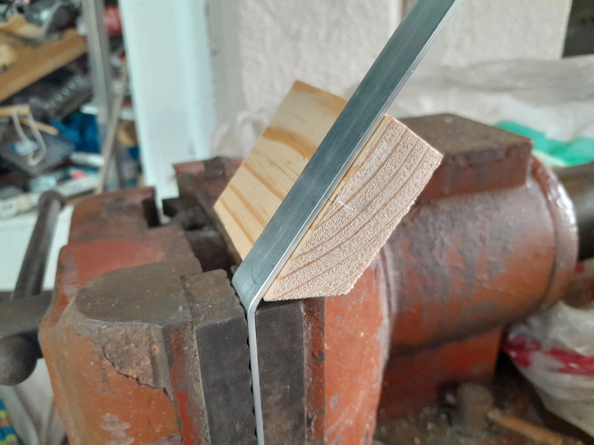
- Then I used that score mark to facilitate the bend, ensuring that it was sharp.
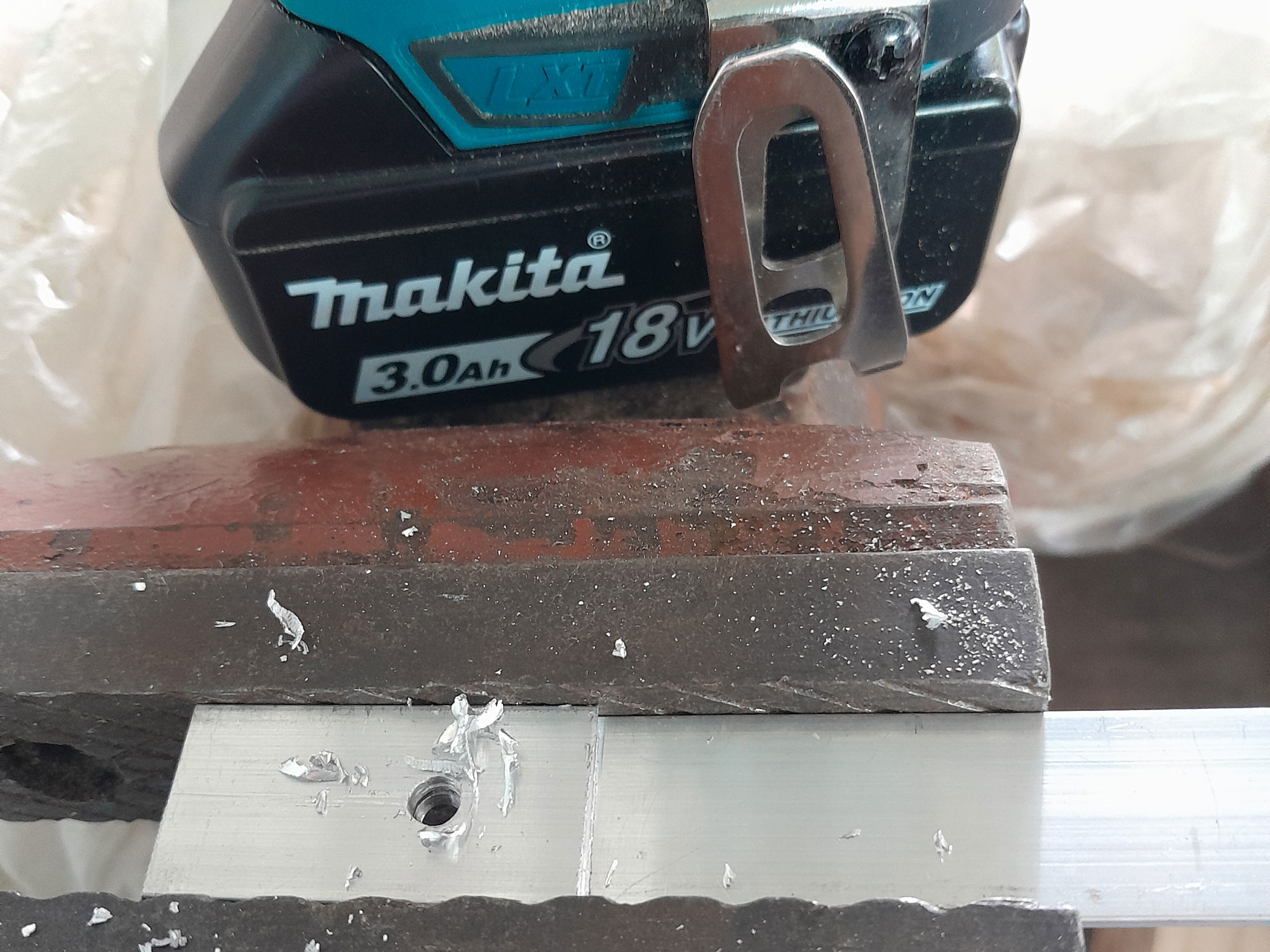
- I repeated the process around the hexagon, and trimmed off the little excess left over from where the other end of the strap meets the other side of the foot. I drilled a guide hole in it about 30mm from one end, ensuring it was centred, and used that as a template to drill the other holes for the strap securing screws. For aesthetic reasons, they need to be centred on the centreline of the strap and the same distances from the other edges of the corners, so they all line up properly.
- The use of the offcut as a template will ensure accuracy.
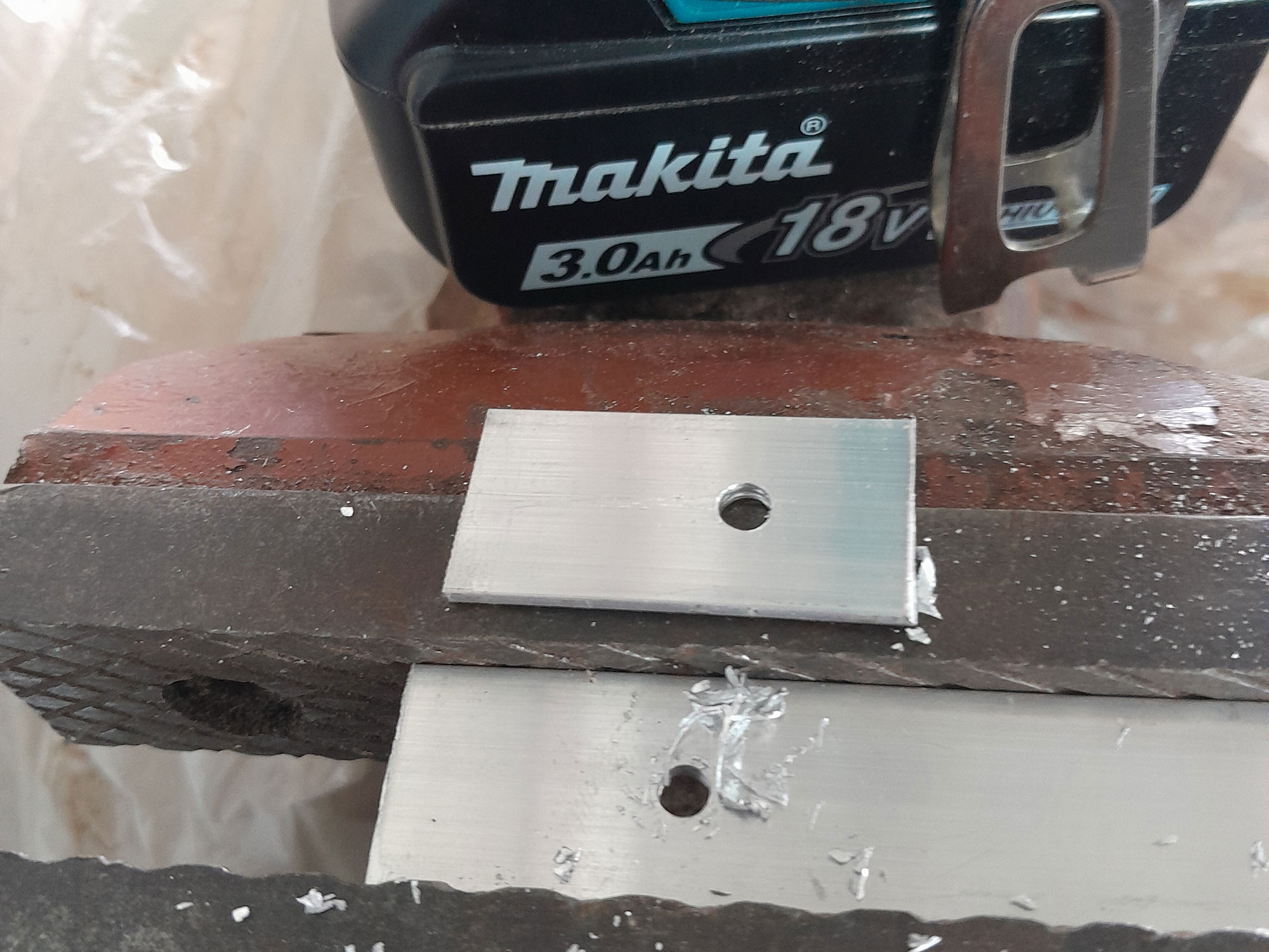
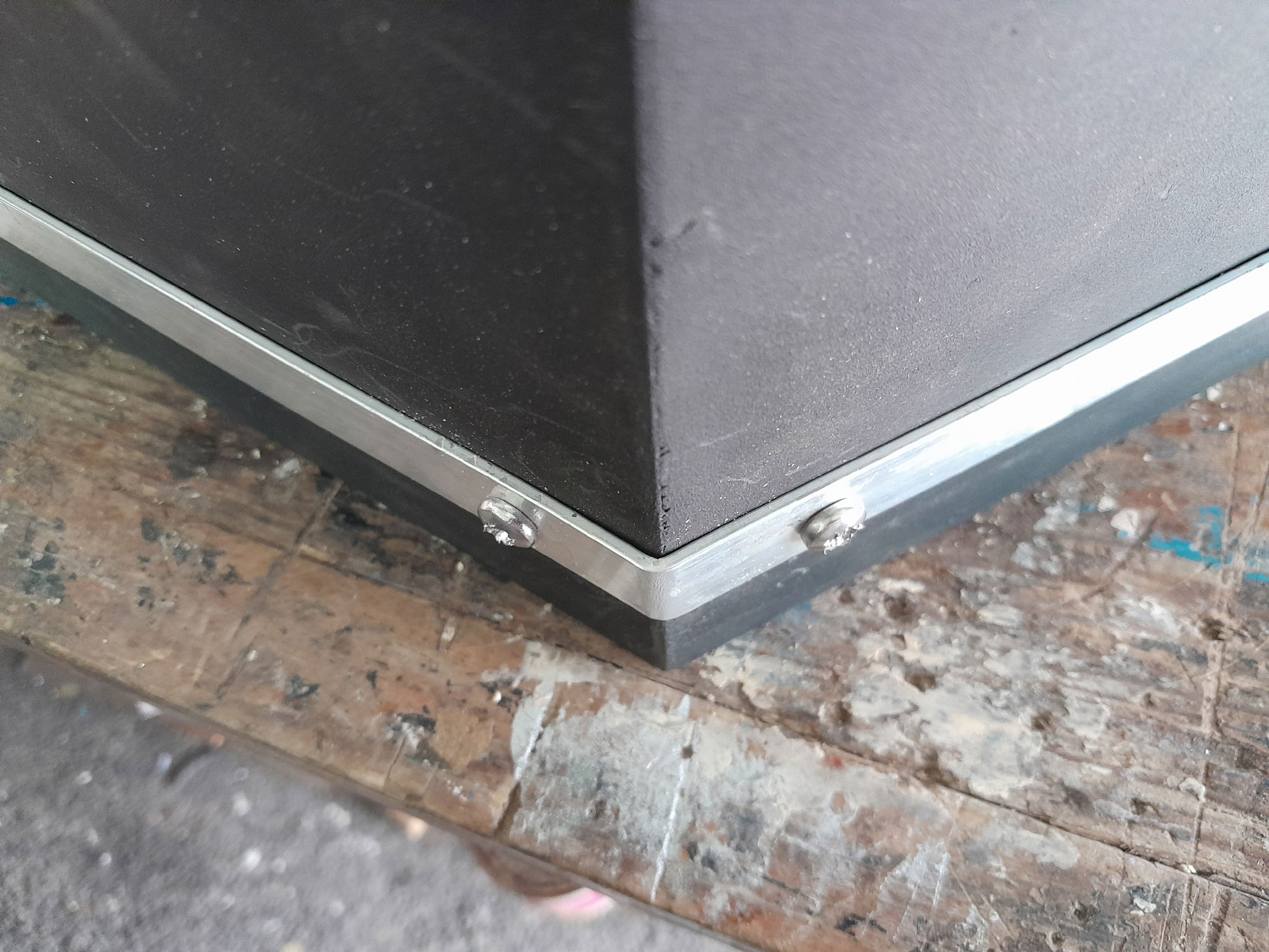
- See?! They line up properly.
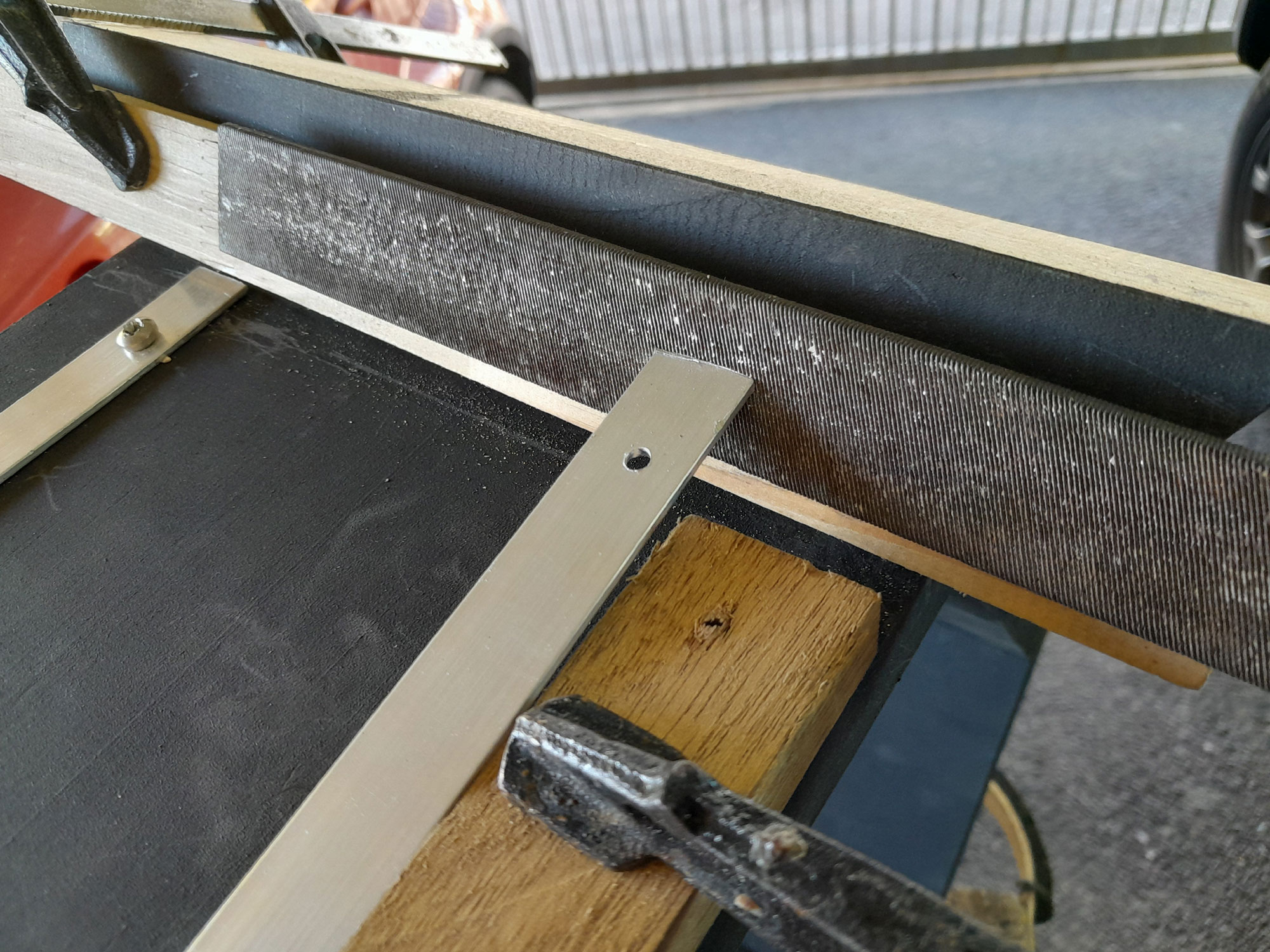
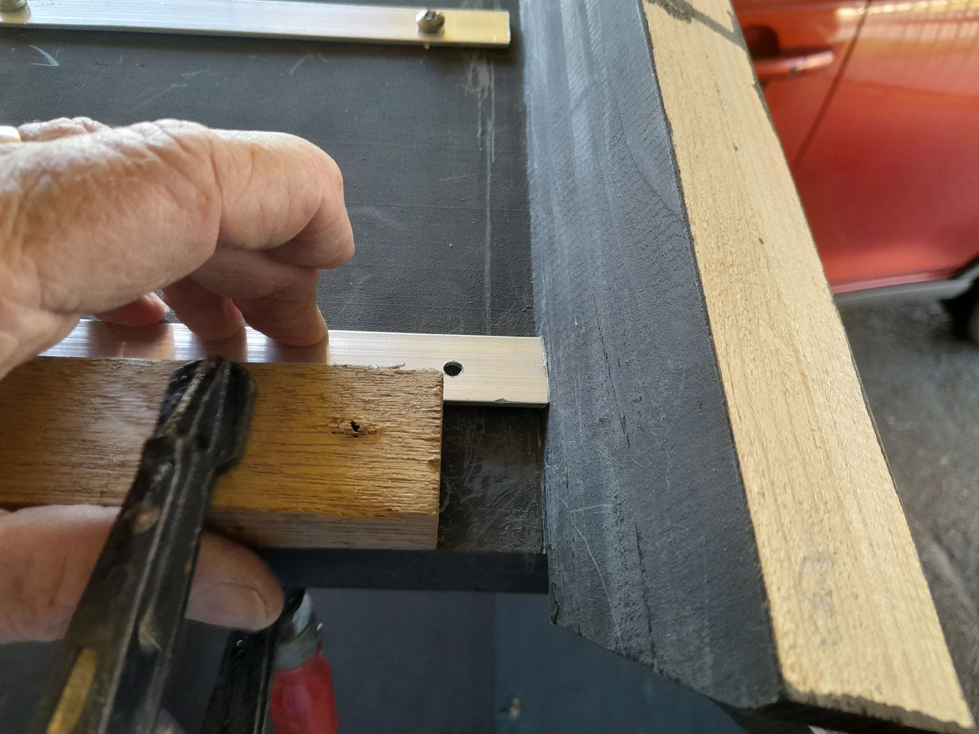
- I trimmed the other end of the strap slightly long, and then used a metal flat file to file the end own, at a 30º angle to meet the foot. Use a piece of 3mm ply offcut or similar to prevent the file marring the leg’s surface while you work the file back and forth.
- It required quite a bit of filing… checking… filing… checking, before I got the strap to meet up exactly as I wanted it to.
- I used the leftover 22x222mm wood used for the main construction, to cut two lengths of 22x222mm, with bevelled surfaces. These would become the sides for the tinder section when the unit is used as a wood rack, and as side stays for the tray when it is used as a book rack-cum-wine rack-cum-side table. I drilled two holes in each for 40mm screws to secure them to the top of the unit. I pre-painted the sides, fixed then to the outer edges of the pinnacle of each hexagon, filled the holes and once the filler had cured, touched them up with a little paint.
- Then I bolted the two hexagons together. This shows the hexagon end of the bolts… the other side uses the dome nuts. This ensures that neither end of any of them would damage any books.
- Now for the tray… I cut a piece of ply, as per the materials list, to the dimensions as listed there – namely 222x358mm. The tray needs to be a reasonably loose fit… if too tight, it will be difficult to place between the two sides, and difficult to extract – which could lead to spills when placing it on the unit or removing it. The handles are aluminium to match the bands used on the unit.
- I marked the centrepoint of the handles and the centre point on the tray base and drilled the securing screw holes in the base, just 4.5mm in from the edge.
- Then I cut the two ends and secured them in position, first scraping off the layer of paint to a width of 9mm so that glue would adhere properly. (Of course it would have been easier to assemble and then paint the unit before attaching the handles, but I had a senior moment – I make these mistakes so you don’t have to.)
- I followed with the two sides, mitred to fit neatly, and with the paint removal repeated. I clamped the sides firmly as the glue cured, and later used 20mm panel pins to secure the sides and ends to the base. Then, for the handle securing screws, I very carefully drilled through from the underside of the base, painted the tray and once the paint had dried, fixed the handles to it.
- And finally finished the tray off with a self-adhesive felt pad on each corner.
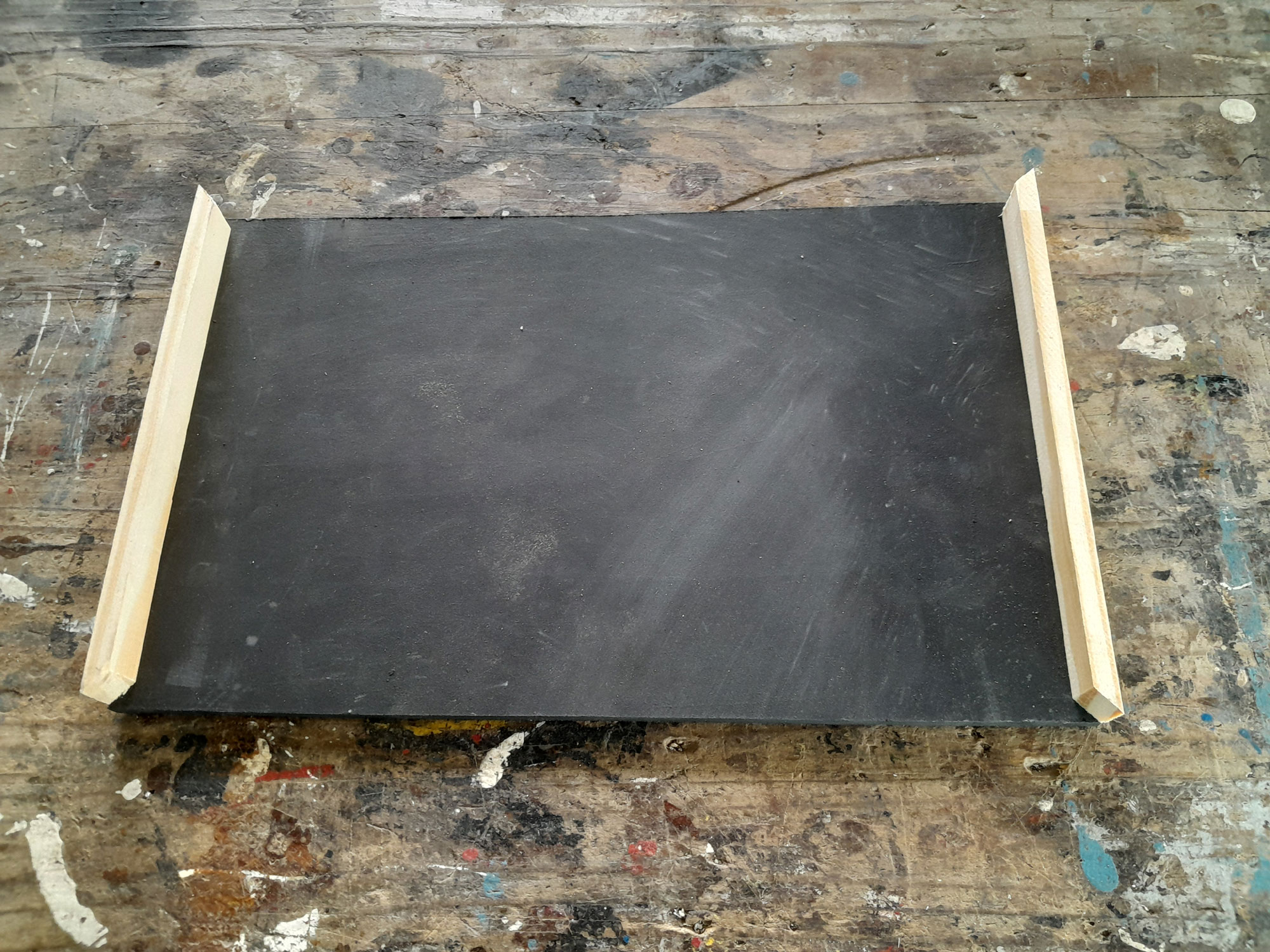
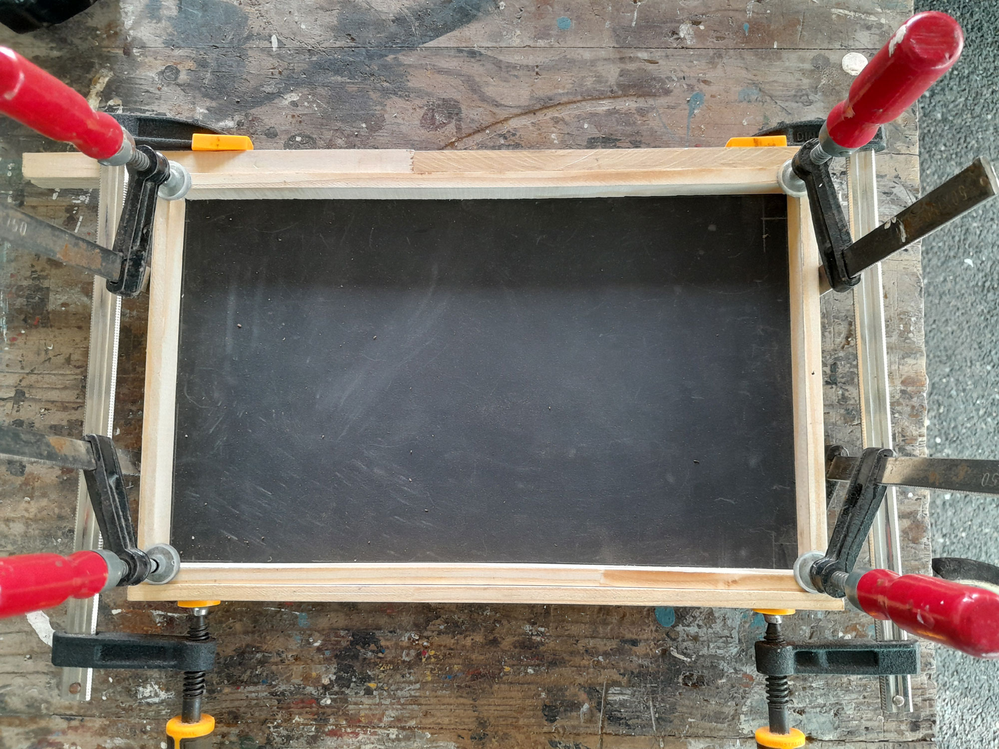
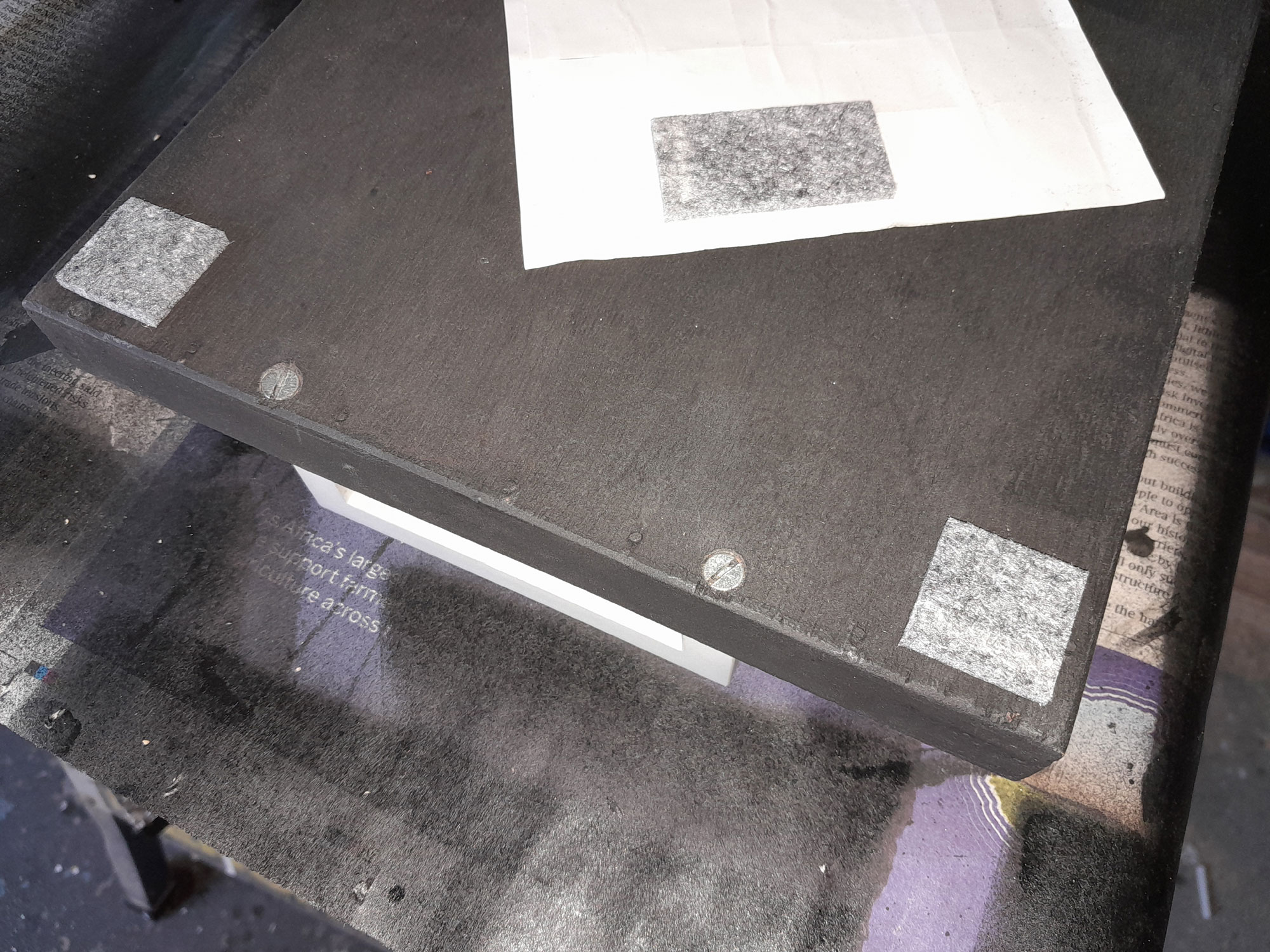
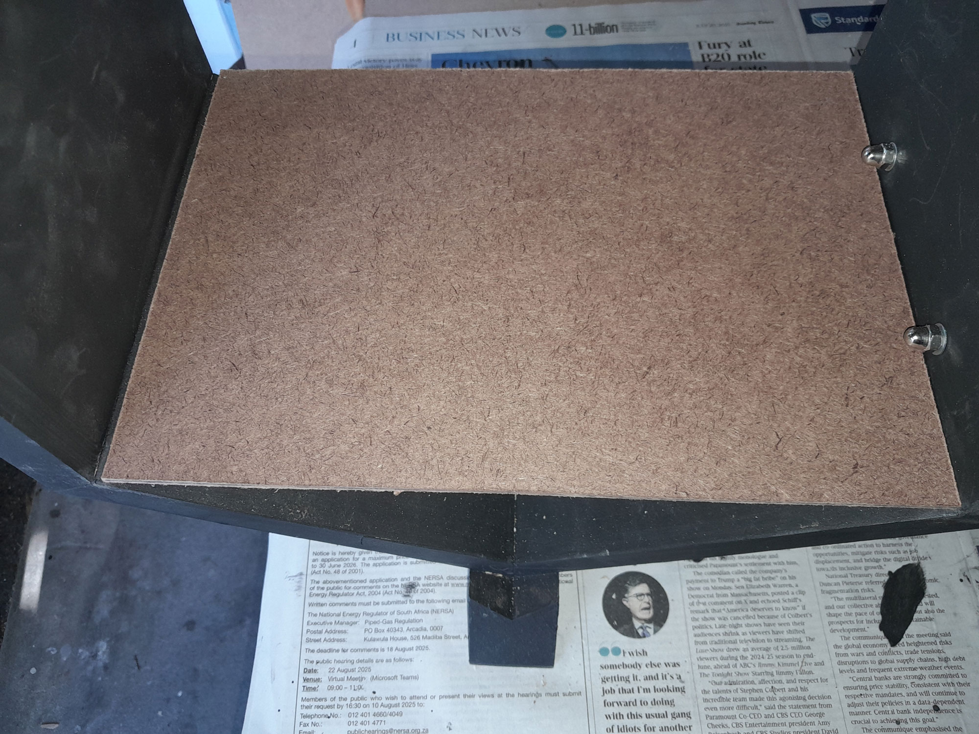
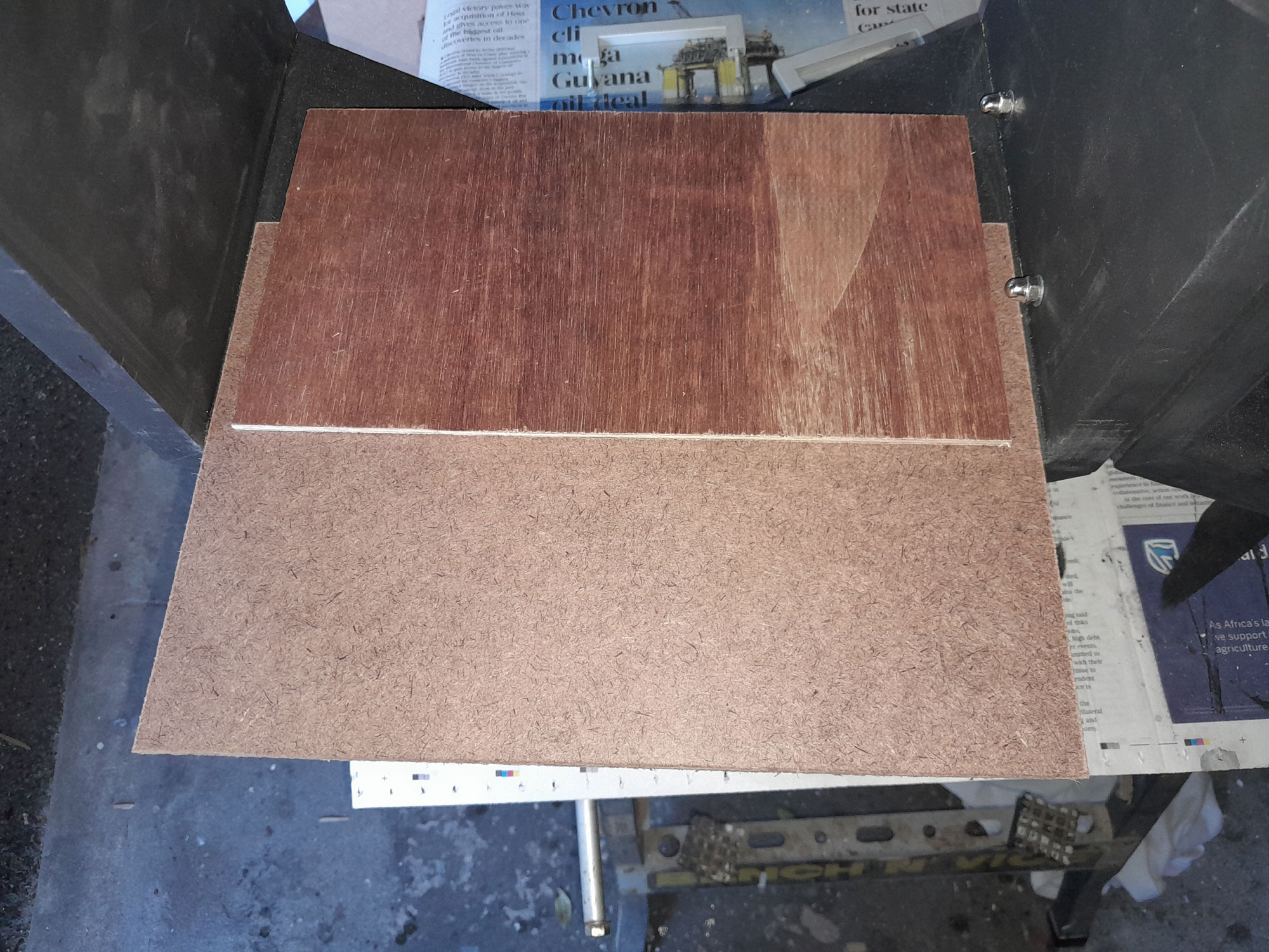
- The shelves are far easier – and quicker… I had some offcuts of tempered hardboard handy, so I cut two – each 222x315mm.
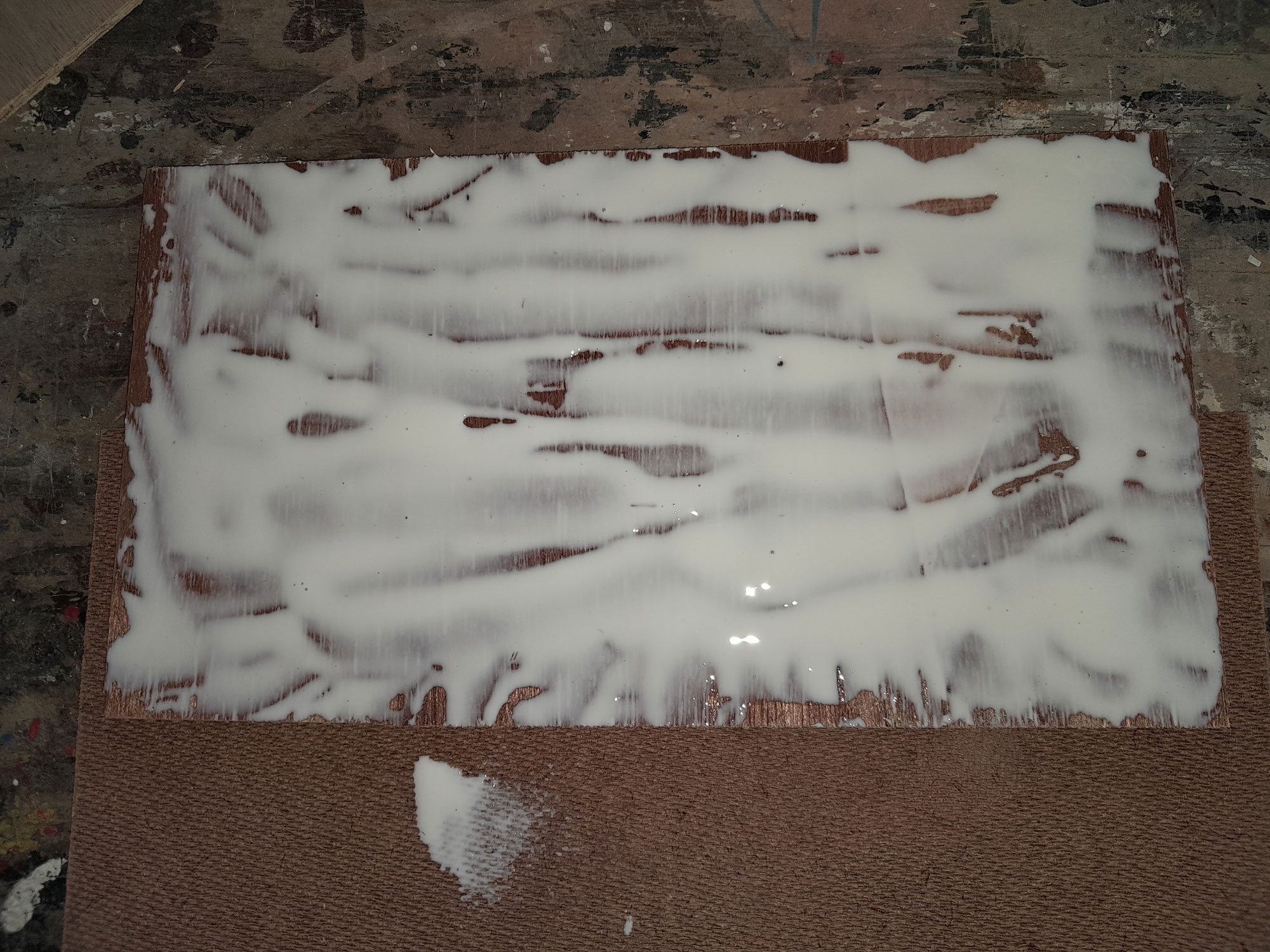
- To reinforce them, I glued a sheet of plywood to the underside of each…
- I ensured the glue was spread right across the ply.
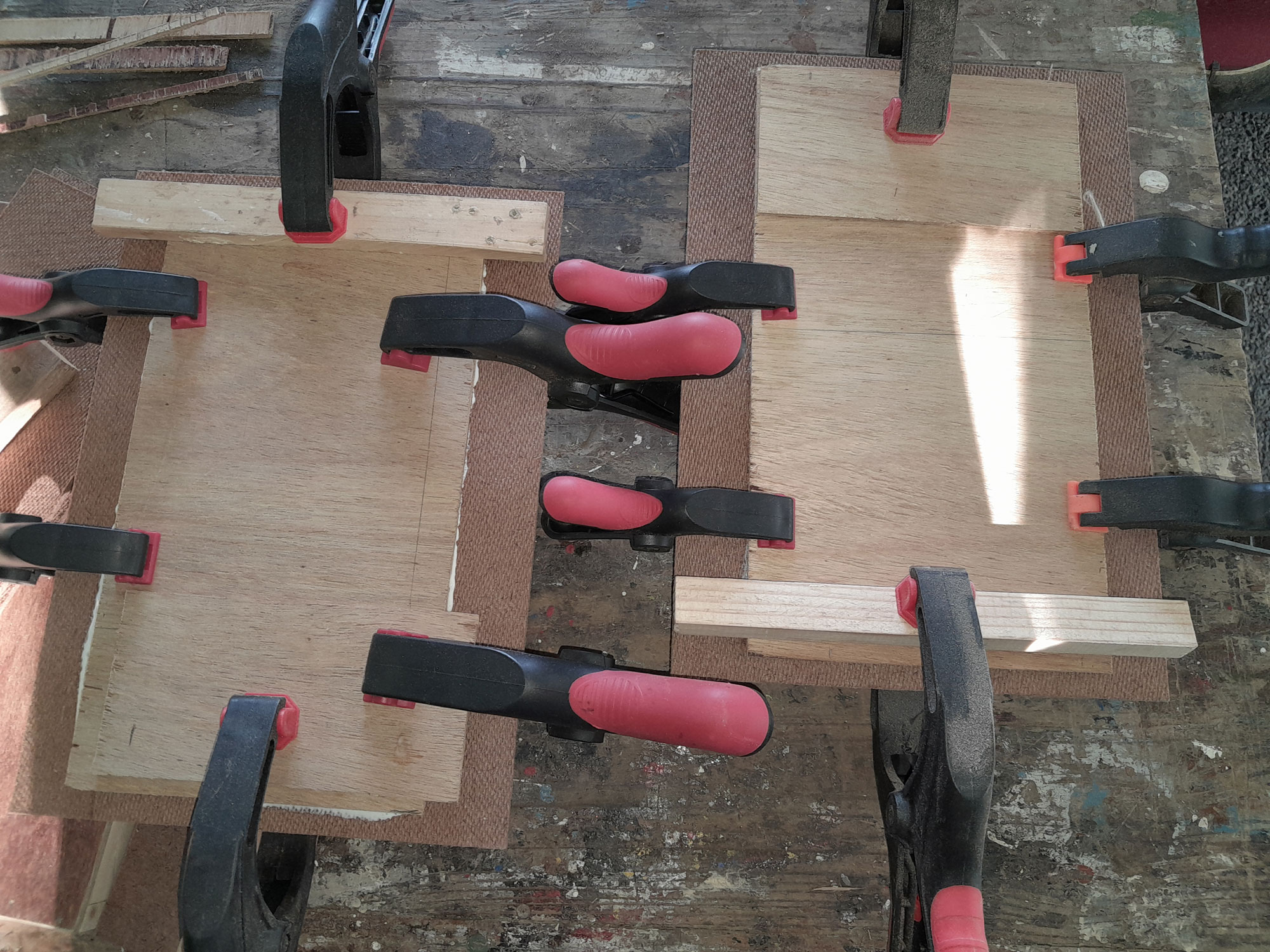
- Then I clamped the pieces to the shelves, left them overnight for the glue to cure and the next day, painted them. Job done!
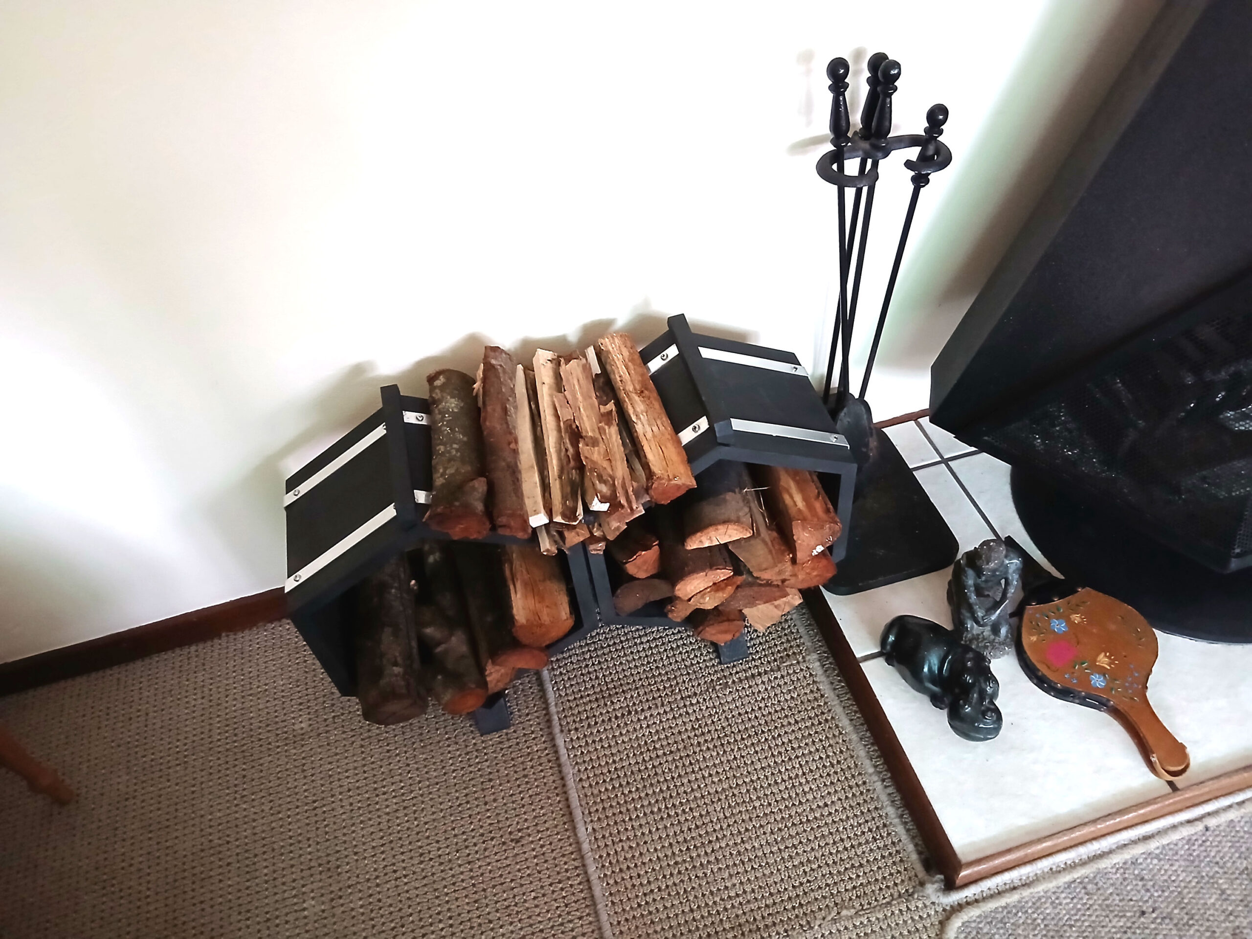
- You can use it as a wood rack
- You can use it as a book rack and/or side table
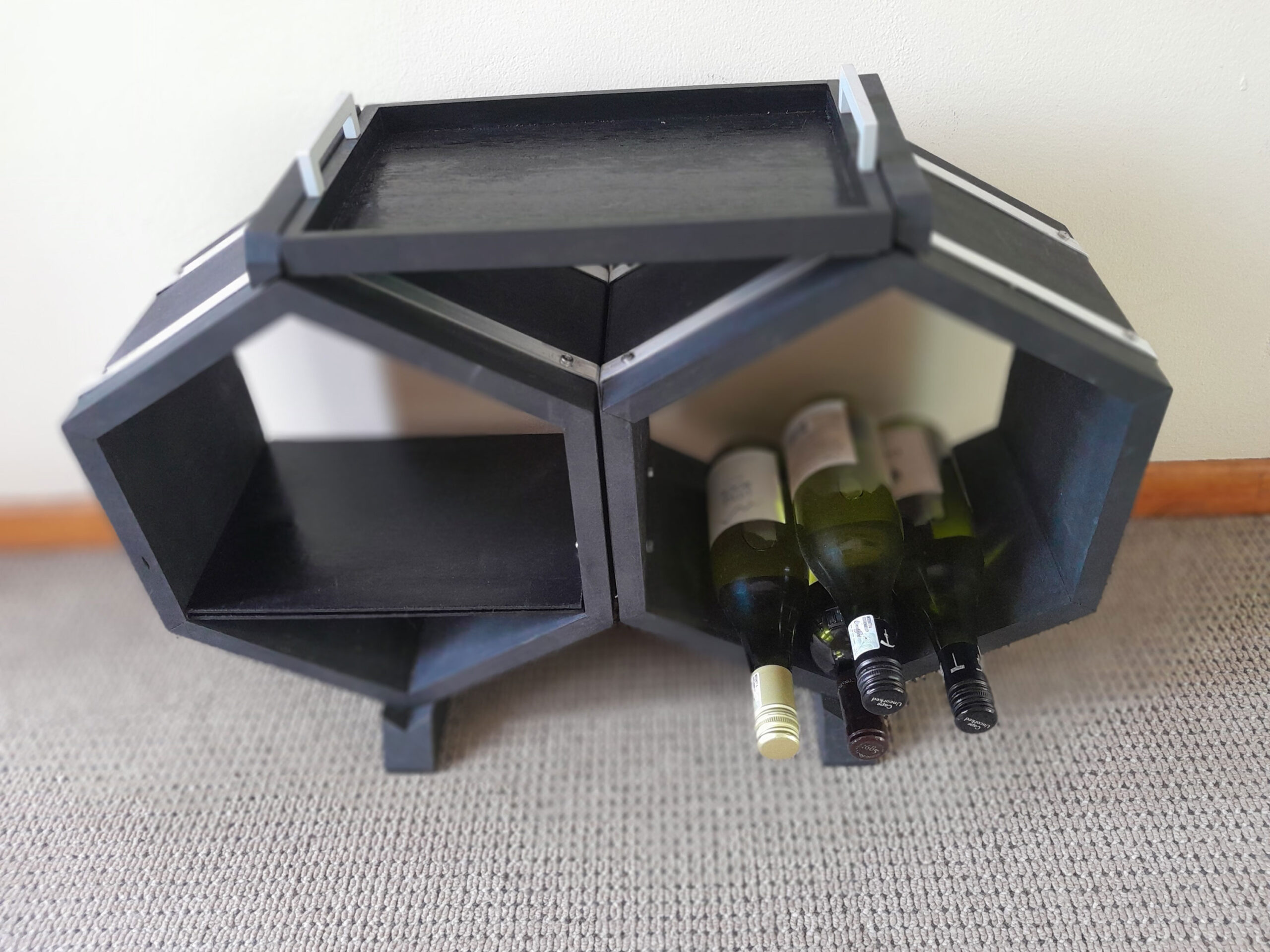
- You can even use it as a wine rack – a unit for all seasons, indeed.
Panel:
These materials are available at Selected Mica Stores. To find your closest Mica and whether or not they stock the items required, please go to www.mica.co.za, find your store and call them. If your local Mica does not stock exactly what you need they will be able to order it for you or suggest an alternative product or a reputable source.
Project guide
- TIME: 1 week plus
- COST: R750 – R1000 (depending on whether you include the aluminium straps as well, or if you add to the number of hexagons)
- Skill: 4
- Assistant: No
Tools required:
Jigsaw, mitre saw, sander, drill/driver (cordless or mains), strap clamp or luggage strap, masking tape or luggage tape – to secure the hexagons while their glue cures.

It’ll be all white on the night*
Make this headboard or one to your own design, to add that little bit extra… the finishing touch, if you will… to a bedroom.
It is all held together with dowels and glue, the only two metal parts being the screws in the feet on the legs to attach the doorstops to the feet.
*The boss – SWMBO (She Who Must Be Obeyed – pronounced “Swimbo”) – or “may waif” in upper-class English, said originally that she wanted the headboard to be all white. I, being the rebellious and recklessly brave character that I am, threw caution to the winds, and decided to do what you see here – a mix of white, and varnished meranti. When she saw it for the first time, I hurriedly gabbled, trembling, “I can paint it all white… if you like”. She, to my astonishment, replied… “No, I like the way you have done it – it ties in with the bedside cabinets. Keep it as is.”
“Jawohl!” I replied, clicking my calloused heels.
So I survived to annoy her at least another day.
Materials**
- SA pine:
- 44×44 – one length of 2400mm cut to two legs of 1000m
- 44×32 – one length of 3000mm cut to two crossbars of 1312mm each
- 12×100 ceiling TG&V*** – two lengths of 3000m cut to 14 lengths of 424mm
- 21x96mm – one length ripped into strips 20mm wide and then cut to fit across the back of the panel to reinforce the join between the TV&G panels and the crossbars and legs
- 22x44mm offcut, cut to four lengths of approximately 90mm long – I bevelled each at 45º
- Meranti:
- 22×44 – one length of 1800mm, to the headboard capping
- 9×19 beading – two lengths of 1800mm cut to fit as trim around the inner front edge of the TG&V panelling
- 8mm dowels – one pack (or five, if you have them already to hand), and one 1000mm length of 8mmØ dowel rod
- Two pine doorknobs – 44mmØ
- Wood glue
- Finish/es of your choice – I used gloss varnish on the meranti capping and on the 9x19mm trim, and water-based white gloss for the rest of the headboard
- Two white doorstops (they are supplied with attachment screws)
- One pack of felt self-adhesive padding, for the wall spacers
**Obviously, should you change the design and/or dimensions, then your materials will change
*** Note: TG&V ceiling panel cross-section dimensions might vary slightly according to the manufacturer… 12x102mm…13x102mm…for example. In this case, the TG&V we used was 12x100mm
Captions:
- First step is to measure the bed for which you are building the headboard. That sounds like an obvious step, but there is not much more disheartening than completing the thing, and finding it is too narrow. Too wide you can live with – perhaps. But too narrow? So… measure away, and in this case, including bedding, the width was a shade over 1400mm
- Height to the top of the bedding on the mattress was 540-550mm.
- In passing, I use one of these writing pads for recording measurements, making the basic design, and so on. Very useful… you can lock your screen, and then unlock it later when the unit is well on its way, and clear it – ready for the next project.
- I cut the legs to the required length of 1000mm, and measured and marked 44mm in from what would be the top of the leg.
- Then I measured off the 1312mm crossbars (1312 + 44 + 44 = 1400mm, for the total width).


- I positioned one crossbar on the one leg and positioned it on the centreline, and on the line just marked. On the leg, I had also drawn the lines to position the lower crossbar.
- I used a gauge to mark off the centreline on the crossbar.
- And I confirmed with the router that the fence was correctly set.
- Then I routed a 12mm wide channel, about 15mm deep along entire length of the 32mm edge of the crossbar.
- The end of the bar shows clearly the extent of the routed channel. The TG&V panelling will slot into this channel.


- I then routed the legs in turn, extending from the 30mm from the top, to about 30mm into the lower crossbar position. In passing, I find it a good idea to rout a very short channel, or even a hole at either end of any routing of a set length, as in this case. It prevents you routing too far, as the drop in resistance tells you when you reach the planned end of the channel.
- Here it is, the channel in the leg at the lower crossbar position.
- This is how the routed channels in the legs and crossbars match up.
- Now comes the aesthetically important part… as the TG&V panels have ‘V’’ grooves in them, you need to ensure that the lengths of TG&V are properly centred. If you do not, then you could find the grooves will be “off-centre”. So, mark the exact centre point of the crossbar, and position the middle “V” groove of one length of TG&V on that point, as shown here.
- Apply glue and tap the single panel into position, and check and check again and again that it is absolutely vertical – in both planes.


- If it is out by even a fraction, then all of the panels will be out. Once you are 100% satisfied, leave the assembly overnight so the glue cures completely; if you position the other panels before that has occurred, you could shift the central panel out of vertical – and swear! In passing, if the weather is humid, raining and/or cold, allow the glue extra time to cure completely.
- The next day you can fit the rest of the panels, in this case six on either side to make up the thirteen in total. Tap each one into position against its neighbour and glue it in. be sure to check continuously when fitting the lengths that you make sure that are fully seated in the groove and up against their neighbours, and absolutely square on the crossbar. Then you can fit the second crossbar, using glue to secure it in place on the panelling.
- Use clamps to fully seat the crossbars and panelling, again, as always, constantly checking everything is at exactly 90º. Use length of scrap wood lengths as cushions for the clamps, so that you do not compress any part of the crossbars. You can then cut and rip a final length of the TG&V and rip it on each side to fit into the channels you routed in the legs, and complete the panelling.
- The height of the headboard backrest would be 490mm.
- You can now fit the legs… use offcuts of suitable dimensions to be able to correctly position the crossbars on the legs.
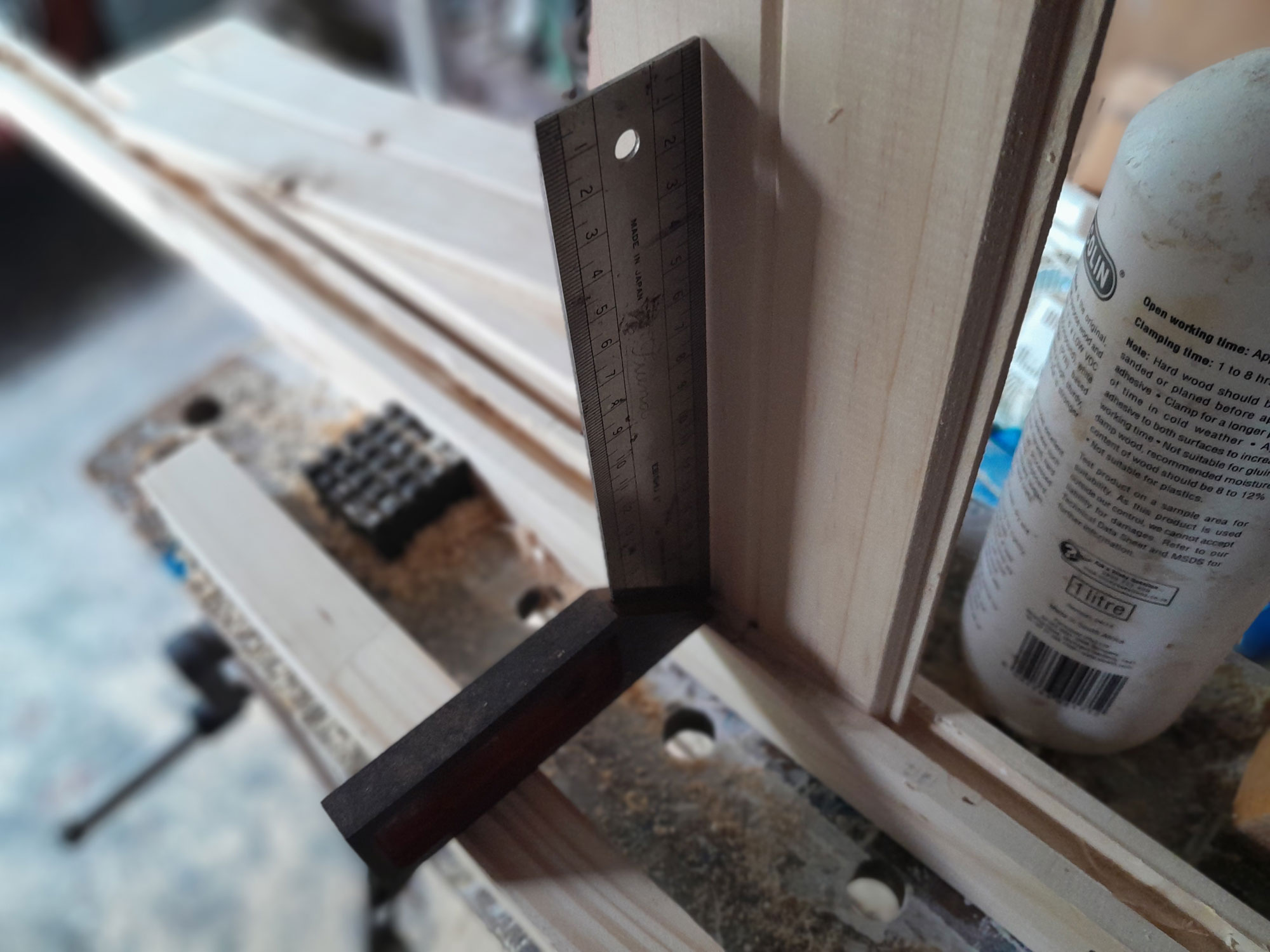


- Then drill two 8mmØ holes right through each leg and into the crossbars.
- Check the depth and drill deeper if necessary. And then cut eight dowels from the 1000mm length of dowel rod. Each dowel should be about 90mm long.
- Then apply glue to the holes, coat the lengths of dowels and the meeting surface of the crossbar where it meets the leg, and using a wooden mallet, tap the dowels into their holes until about 5-6mm is still proud of the surface, as shown here, and allow the glue to cure. However, if you wish, you can seat the dowels fully, to just below the surface, and use wood filler to fill the holes. Once the filler has dried, you can sand it down flush, for a very neat join.
- Apply clamping pressure to ensure the join is solid, but also…
- Measure the diagonals, from the bottom outer corner of each leg, to the top outer corner of the other leg, to ensure that the whole headboard is absolutely true. In this case, both diagonals were the same, namely 1712mm, as shown here. By the way, do not pull the tape when measuring as this can flex the leg just ever so slightly inwards and give you a skrik! No load on them, okay?!


- After completing the joins, I cut and glued in the 12x20mm cover strips around the back of the panelling, mitring the corners, as shown here. They are more to hide any slips with the router than to reinforce the bond between the panelling and the top and bottom crossbars and the legs – that’s my story and I am sticking to it! Note the very liberal use of hand clamps to hold them in position while the glue cured.
- Here’s a corner shot of the above… note that I have not yet sanded down the dowel ends protruding from the legs.
- I used a scrap piece of 22x44mm SA pine to make my spacers. They ensure that the headboard is held clear of the skirting and parallel to the wall’s surface, rather that leaning back against the wall as it would without the spacers.
- On each leg, one spacer is attached just below the top crossbar…
- The other is attached about 100mm up from the foot of the leg. It must be positioned so that it is above the skirting board. If it is positioned too low and comes up against the skirting board you will end up with a headboard leaning back, rather than standing parallel with the wall.


- Now for those protruding dowel ends… I used a pair of side cutters to snip them off.
- Like so…
- I rounded off the top edges and ends of the meranti capping using a rounding-off bit, and drilled an 8mmØ hole in the centre, and 22mm in from the end of the meranti capping. Then I drilled an 8mmØ hole in the centre of each doorknob and applied glue ONLY to the part of the dowel going into the doorknob, wiped off any excess glue and clamped the doorknob on to the meranti (as you can see already with its first couple of coats of varnish). This will ensure that the doorknob will sit absolutely flat against the capping when finally glued into position.
- Once the glue had cured, I could tap out the doorknob, now firmly seated on its length of dowel, and then position the capping precisely on the legs. I could then use the pre-drilled hole in the capping as a guide to drill into the top of the leg.
- Then I drilled five 8mmº holes along the top of the top crossbar.


- I popped a guide pin into each, repositioned the capping on the legs, with the doorknob dowels keeping it precisely aligned, and pushed down on the capping to indent the points on the pin guides in the bottom of the capping. I then marked the front (leading edge of the capping clearly on its underside, and drilled an 8mmØ hole in each position, but just 15mm deep.
- I took a little time off to sand the repaint each doorknob. Sanding is a breeze if you lightly fix the dowel in the drill chuck and turn it on… it saves you having to sand around curved surfaces… the drill does the turning for you.
- Thereafter I applied masking tape around the inner edge of the front of the panelling, and painted the panels, applying three coats. Thereafter I peeled off the tape. Why the tape, I hear you ask? Because that is where the 9x19mm meranti beading will go – and the glue needs to be applied to bare wood.
- I hand sanded the dowels on the legs, so that they were flush with the surface, and sanded other areas prior to painting.
- This illustration shows how the doorknobs, capping, legs, panelling, crossbars come together and the dowels hold it all together.


- Here the beading has been fitted and clamped in position while the glue cured. The beading serves two purposes… not only does it – I hope – enhance the headboard’s appearance; it also removes the sharp edge of the leg, crossbar, panelling junctions, which could be uncomfortable if one’s head meets any of them in the dead of night.
- A close-up of the corner of the beading… rather neat, even if I say so myself.
- This top-view illustration shows how the leg, TG&V panels, back strips and front beading all come together.
- Almost done… I applied the felt pads to the spacers. These protect the wall.
- Even closer to all done… I marked off the centre point of each leg…


- Then I screwed the doorstops into position.
- Here is a shot of the headboard in position, showing off the capping, beading and doorknobs. It also clearly shows how the beading frames the panelling.
- And why the doorknobs? Well, you can use them to hang a torch on…
- Or a sleeping mask…
- Or a phone recharging cable – or all three, to be frank.


- And there we are… all done and dusted.
- From straight on…
- And finally from the other angle.


Tools:
Drill/driver (mains or cordless), router, sander – orbital or random orbital, jigsaw or circular cut-off saw or mitre saw, wooden mallet.
Project guide
- Difficulty: Experienced
- Estimated time: About two weeks or so
- Cost: Depends on the cost of the materials from your Mica and the dimensions and design of the headboard, but for the example featured here, about R1000
Panel:
Mica Stores stock the timber, dowels and so on that you need. To find your closest Mica and whether or not they stock the items required, please go to www.mica.co.za, find your store and call them. If your local Mica does not stock exactly what you need they will be able to order it for you or suggest an alternative product or a reputable source.
How’s this for a grand stand?
This pot plant stand has been designed to suit a particular tray/pot size, but can be resized to whatever diameter tray and pot you like. Just beware of making it too high and too narrow, as this would be more unstable than a slightly squatter version such as the one featured here… which is very stable.
In this particular case, the tray is just over 345mm in diameter, so the stand’s arms were spaced 360mm, to allow for a neat fit, but allowing for a little clearance… namely, about 7mm or so one each side.
Naturally, if you decide to make one of these for your own pot plants, you can adapt this stand’s dimensions as you see fit… diameter, height, lower rest height from the ground, and so on.
In this case, arm spacing is 360mm, so total outer width of the arms is 410mm, total height is 653mm, comprising top and bottom caps, top arm of 65mm, upright of 450mm, feet of 75mm, and two T-connectors, each 25mm.
The lower cross bar assembly is ideal for a second pot plant, if you wish… perhaps a more erect one rather than a trailing one such as a creeper, which could be stepped on. The thing is that contrasting foliage can in its own right be most attractive.
Materials:
- Aluminium – 25mm square section: Two lengths of 2.5m, cut to:
- Four tops – 65mm
- Four legs – 450mm
- Four feet – 75mm*
- Two cross arms – 360mm
- Four short cross arms – 158mm
- Polymer 25mm square connectors:
- Eight T-connectors
- Four braces (cruciform 25mm X connectors were not available
- Eight male end caps
- Stainless steel pan head Pozidriv self-tapping screws – 5mm x 16mm (size 12×16)
*I actually could have made the feet longer, say 100mm or so, but didn’t.
Method:
- Here are the components. There are quite a few of them, but once all the cutting is done, and braces attached, assembly is quite quick.
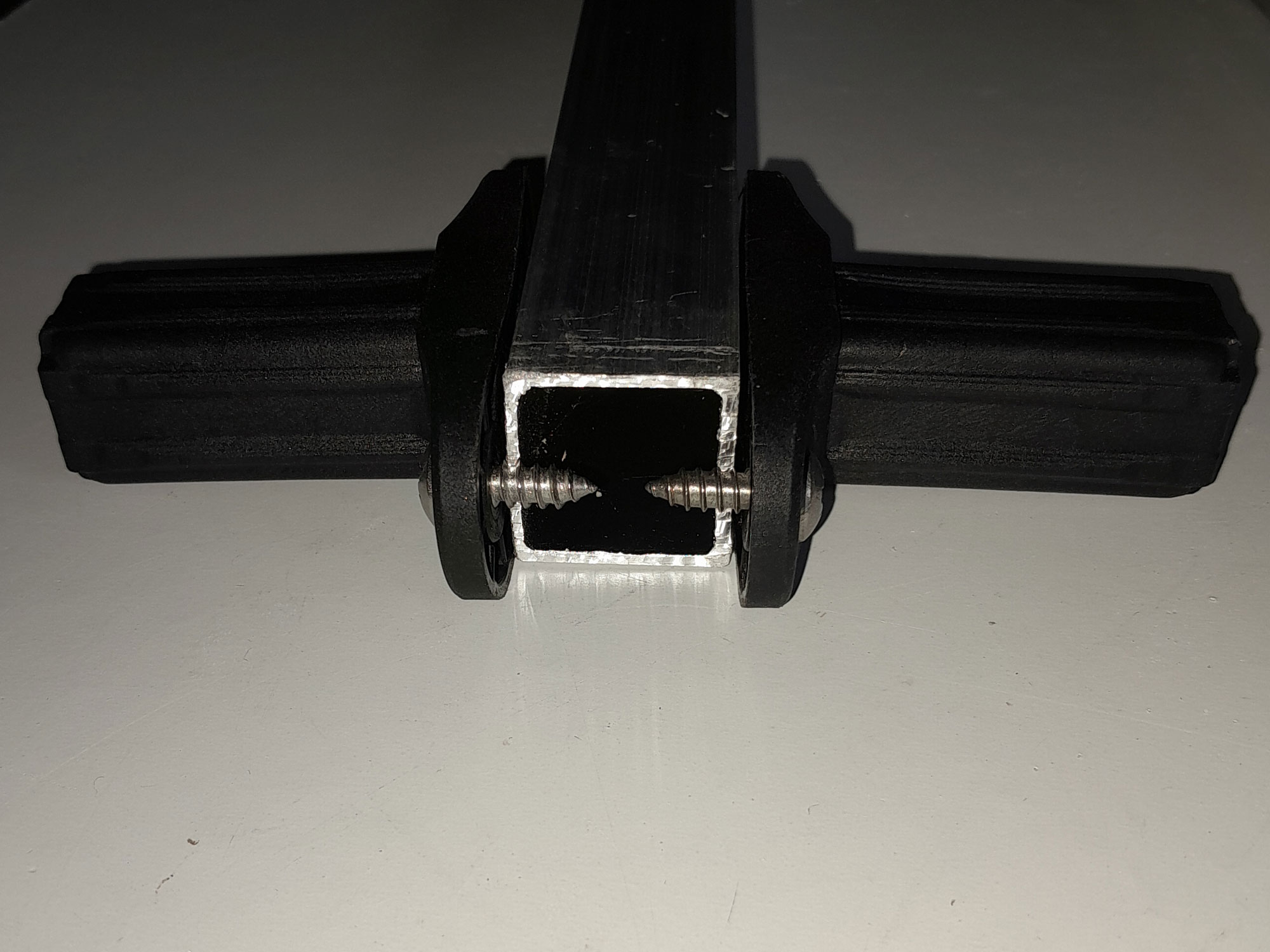
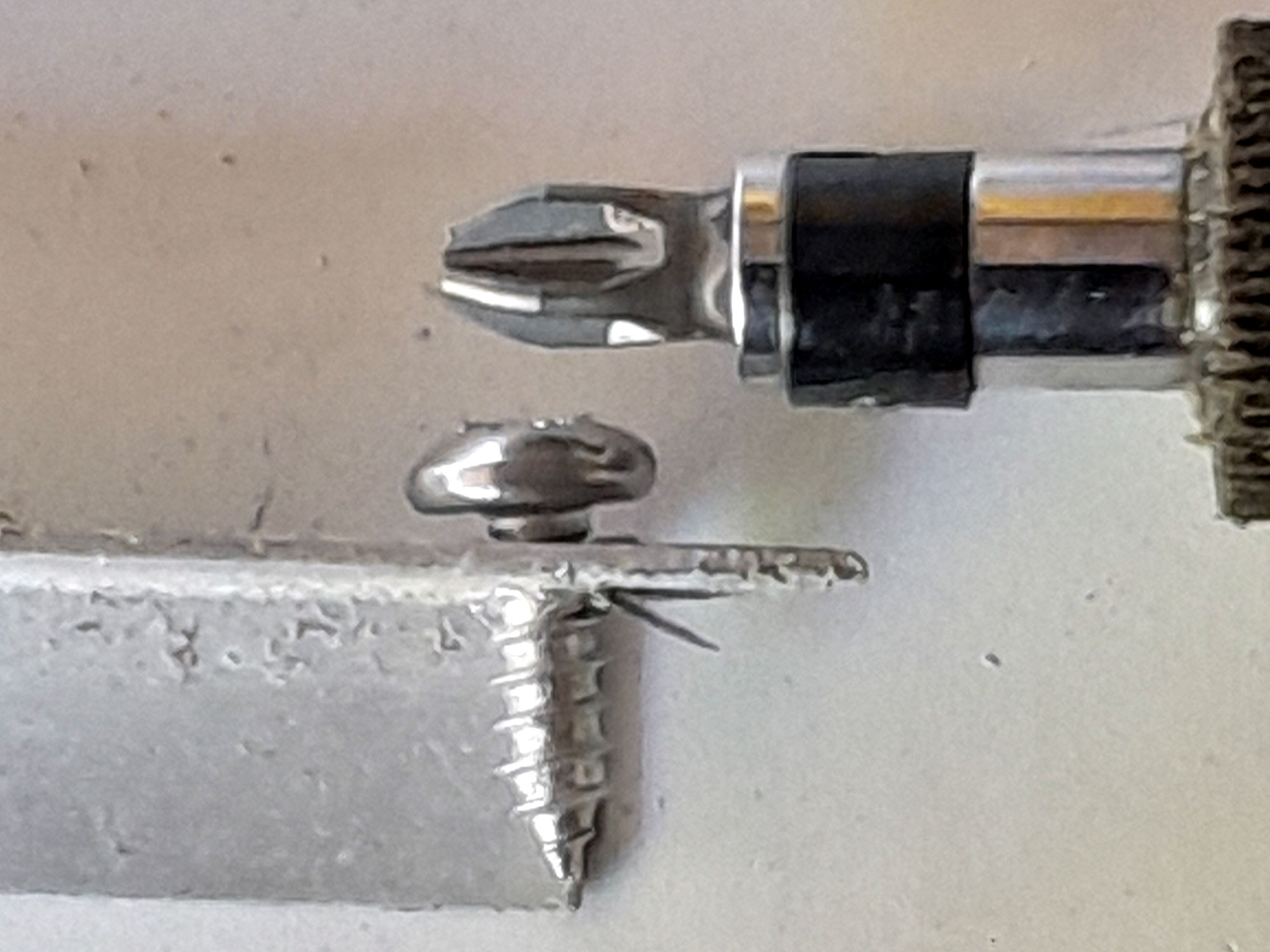
- First of all, I checked that the 12×16 securing screws would fit – i.e., not meet – when used to secure the braces; naturally, the braces would have to align perfectly for the stand to accept a round tray. As you can see, the screws will not meet. If you find that you use a different screw size and/or different square-section aluminium, and the screws you are using do just meet, the solution, when securing the braces, is to follow the same procedure as detailed below, drive one screw in through each pilot hole to establish a thread. Then remove it, and nip off the tip, so you can still insert the screw into the pilot hole, but the tips do not meet in the middle.
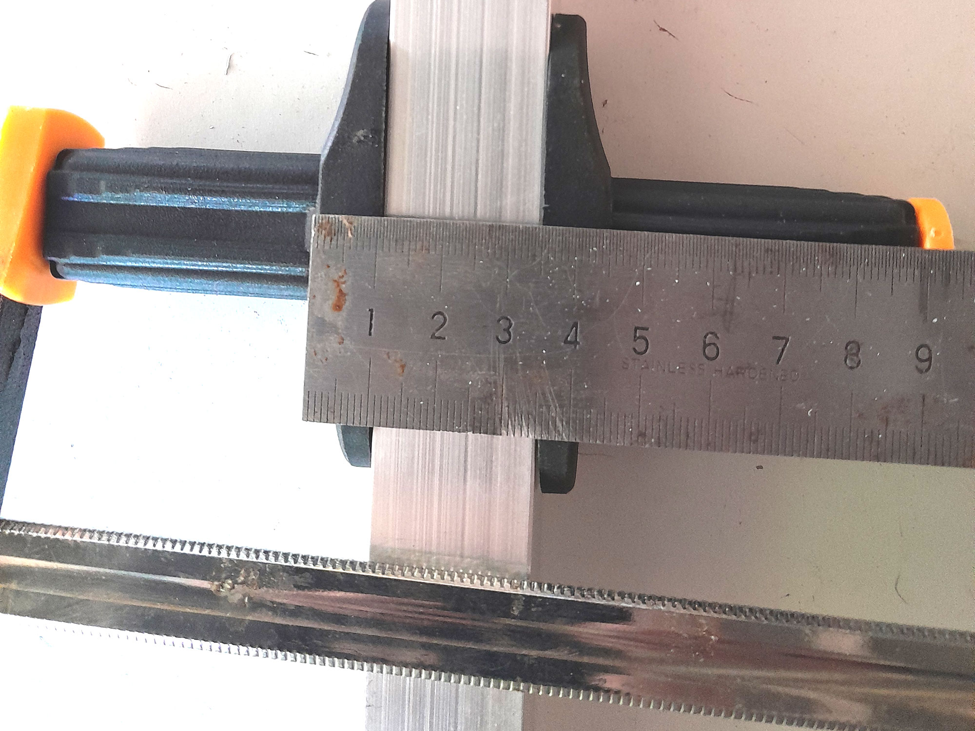
- The four tops would be just long enough to be seated firmly on the T-connector, and accept the end cap. I placed them together, as shown, and measured off the clearance – i.e. the length of each top. I added a couple of millimetres to ensure no hassles later on, to establish how long each top would need to be.
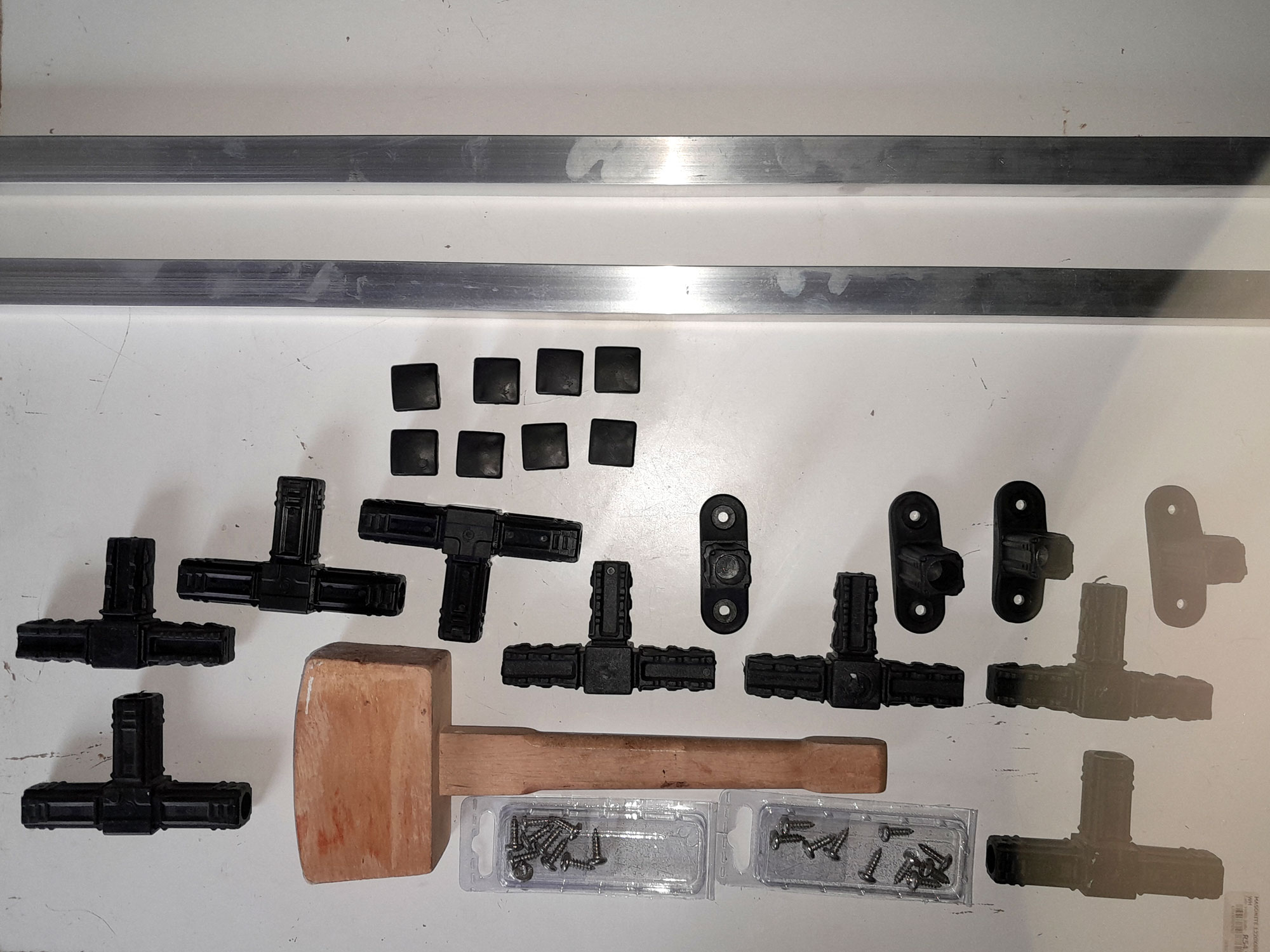
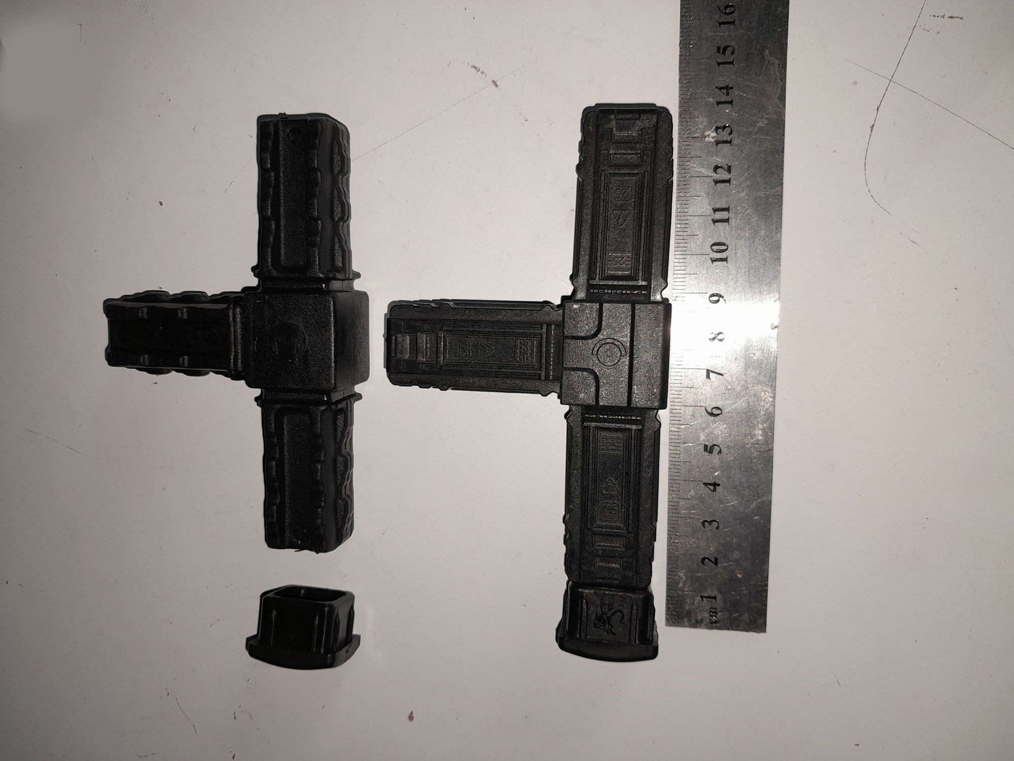
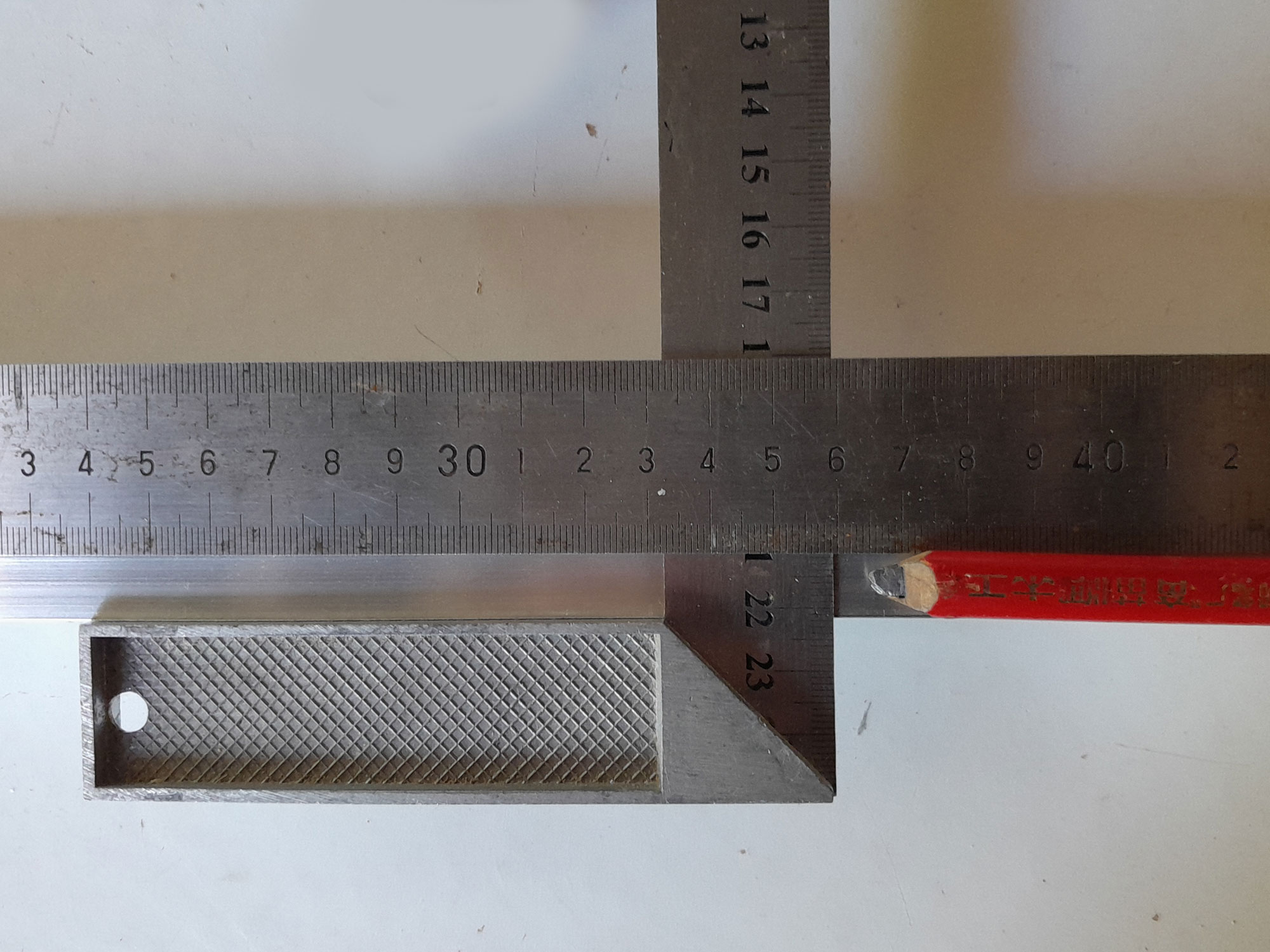
- Then I measured off and cut the first 360mm cross arm.
- As with all the cut ends, I filled down the ends where the saw had left a slightly sharp edge.
- Having cut both cross pieces, I positioned the braces dead centre, and took the opportunity to measure the total width of the braces and cross arm when fitted together. This would give me the length required for each of the four short cross arms – 158mm.

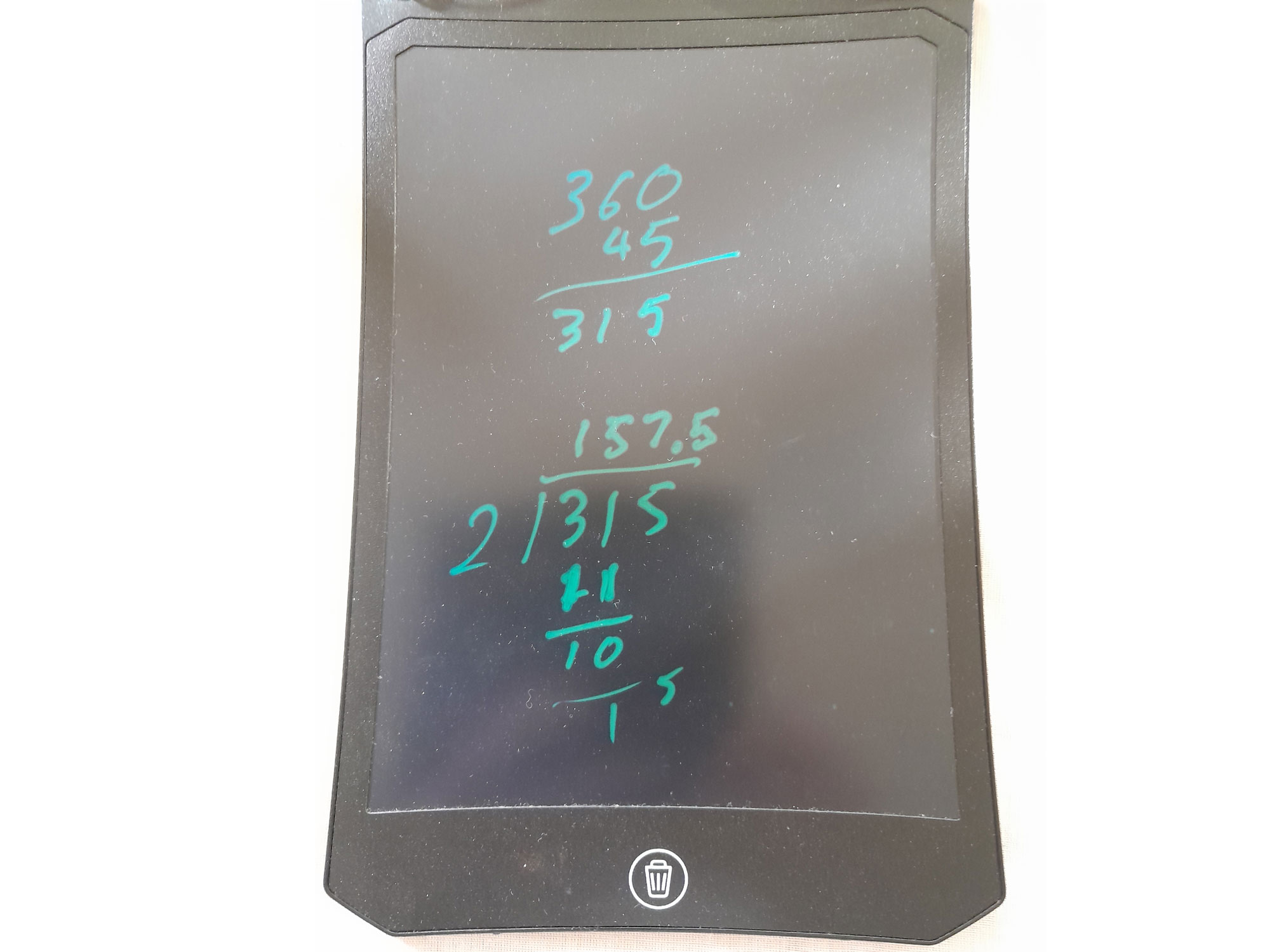
- In passing, a LCD writing pad such as this one is great for doing calculations etc. and doesn’t waste paper. You can save your calculations, or simply clear them, ready for the pad’s next use.
- I measured off all the other lengths required and cut them, then lined up the four legs, cross arms, short cross arms, tops and feet in turn to trim each set to precisely the same lengths. Any difference in any of the individual pieces in each set would put the stand out of kilter, even slightly, and could result in hassles in assembling it properly.
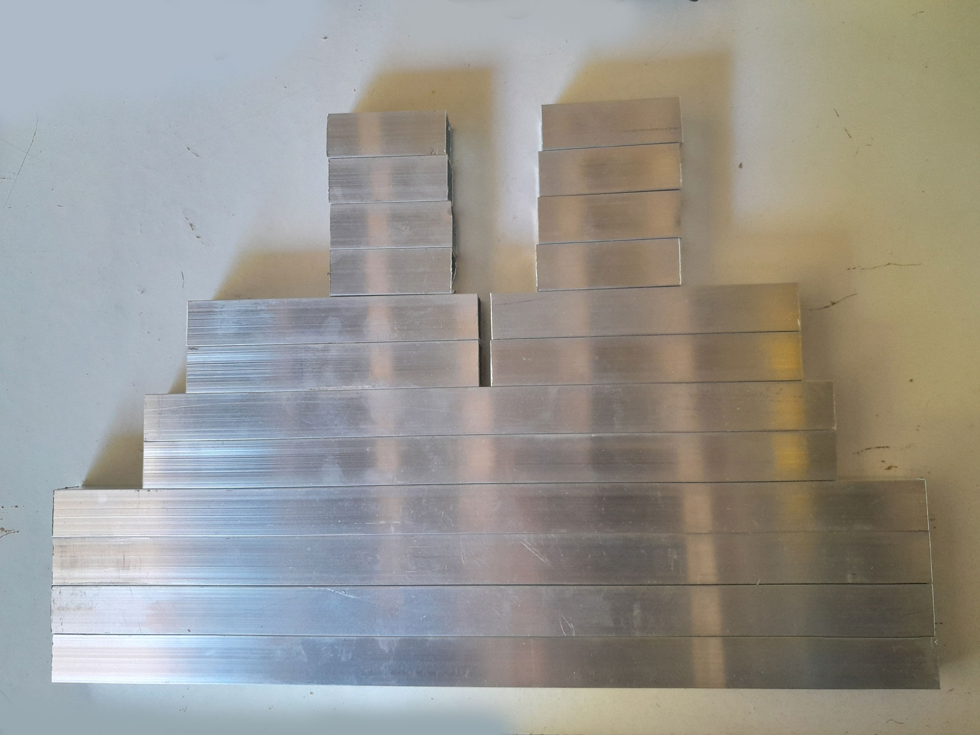
- Here are all the pieces cut to length and ready for assembly.
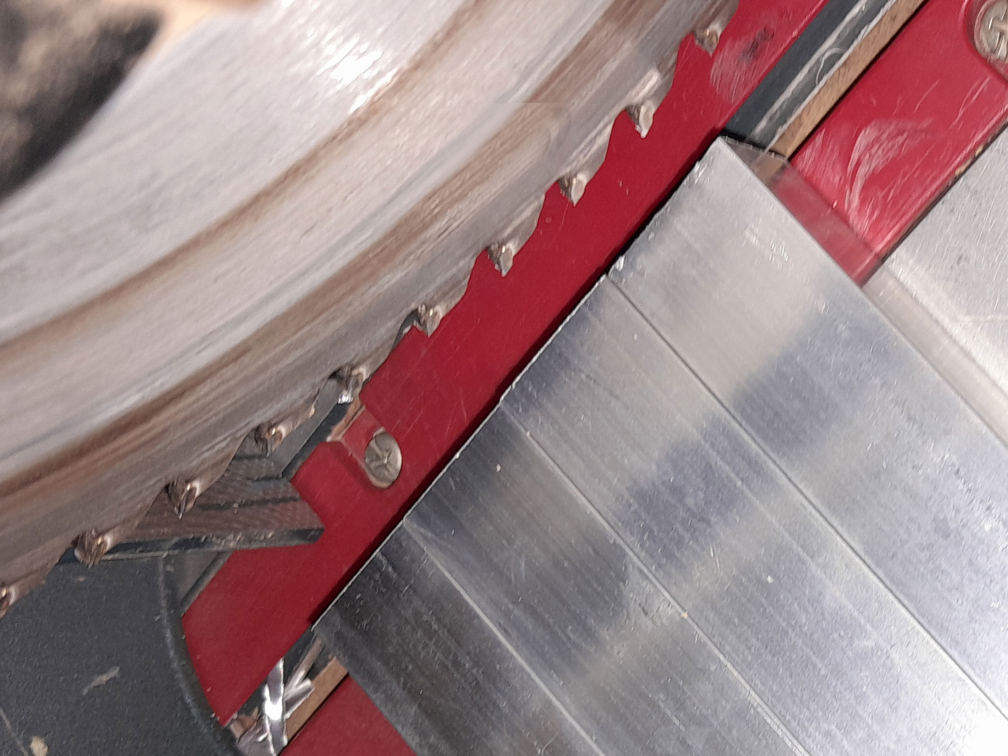
- I did a dry fit of the cross arm assemblies to ensure that once assembled, they would each be 360mm from end to end across both axes.
- Here are the respective lengths of the top (left) and the slightly longer foot (right). Upon reflection, I could have made the feet longer, but they do work fine as is.
- I measured and marked the centre line of each long cross arm – 180mm.
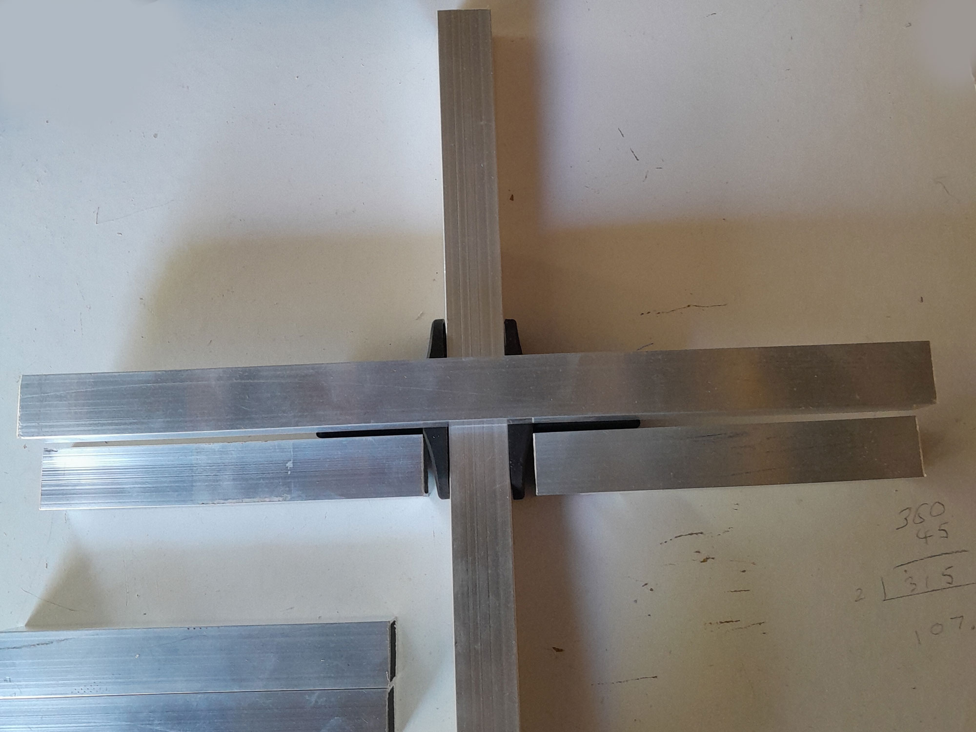
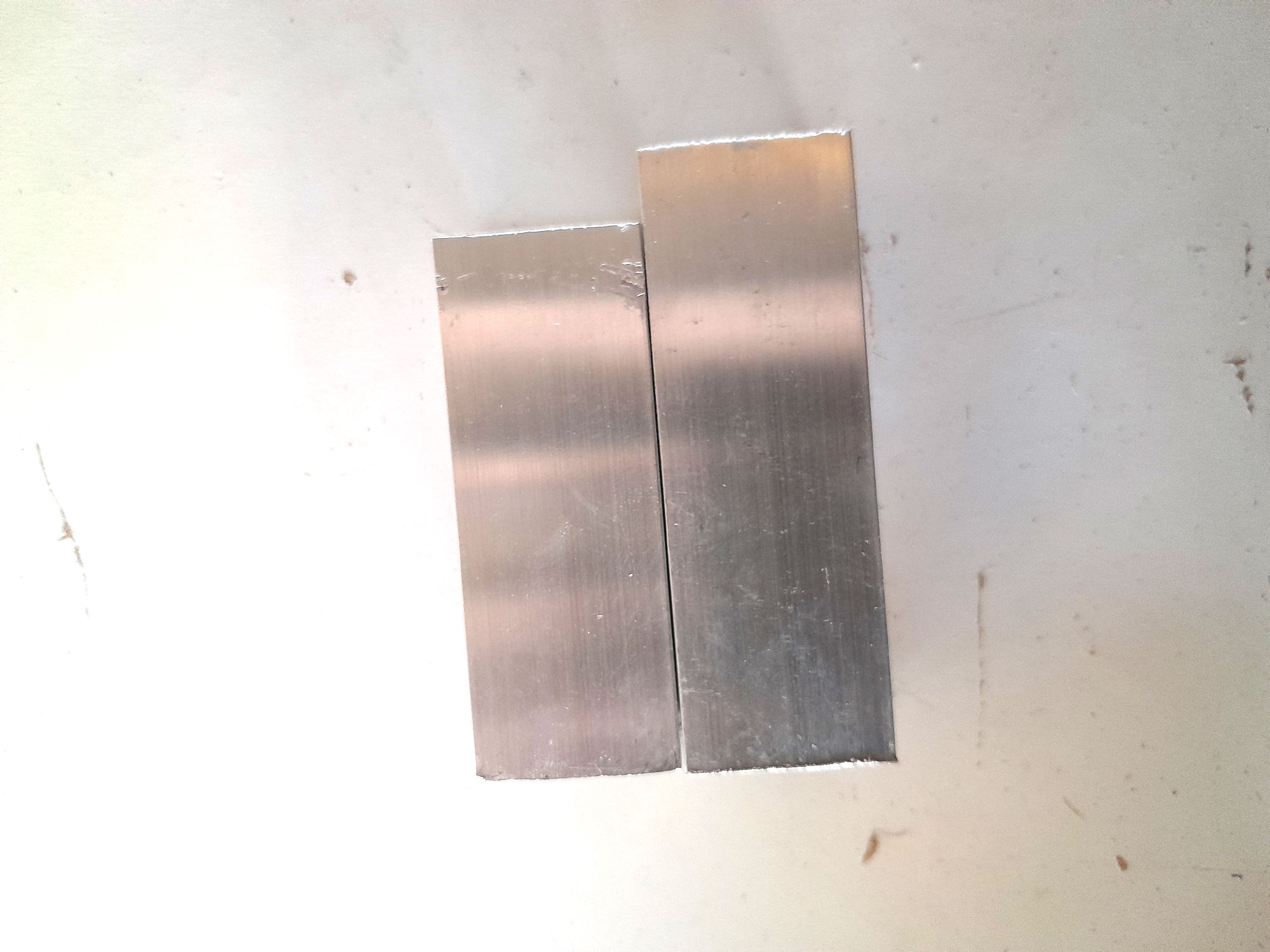
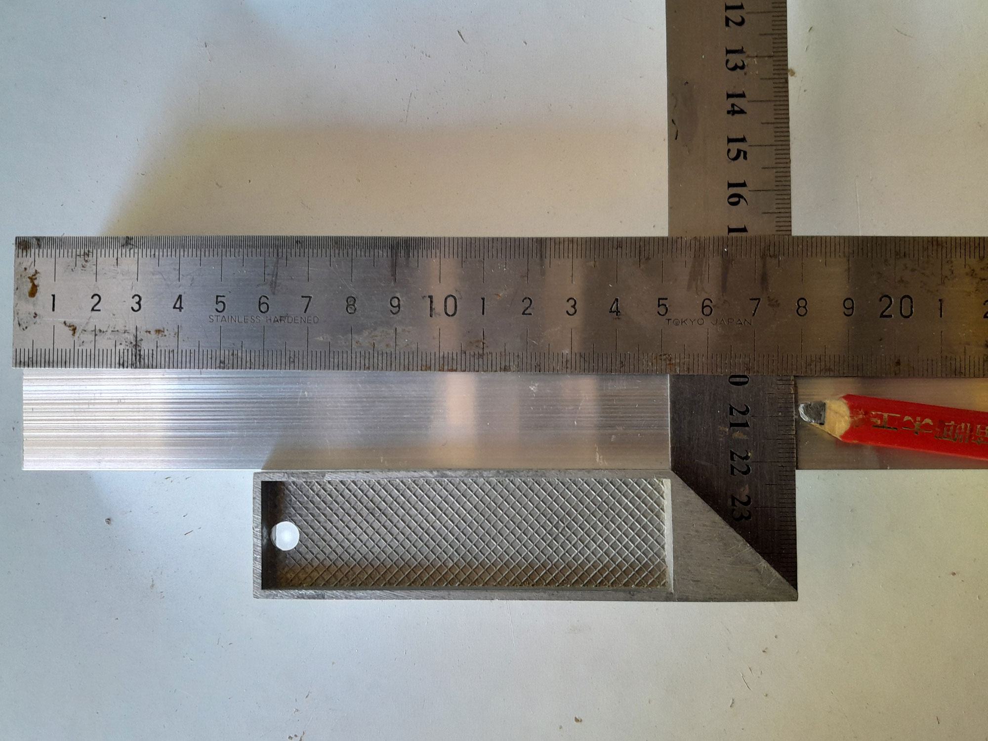
- Then I VERY carefully measured the spacing for brace securing screws – 26mm from the centre, as it turns out.
- Then I measured the 26mm from the centre line on each long cross arm.
- You can use a centre punch designed for use with a hammer, or a spring-loaded version, and a gauge to ensure you mark (indent) the exact centre point for each securing screw.
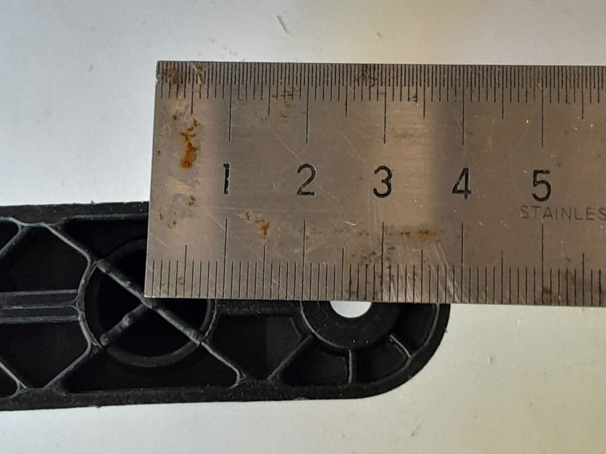
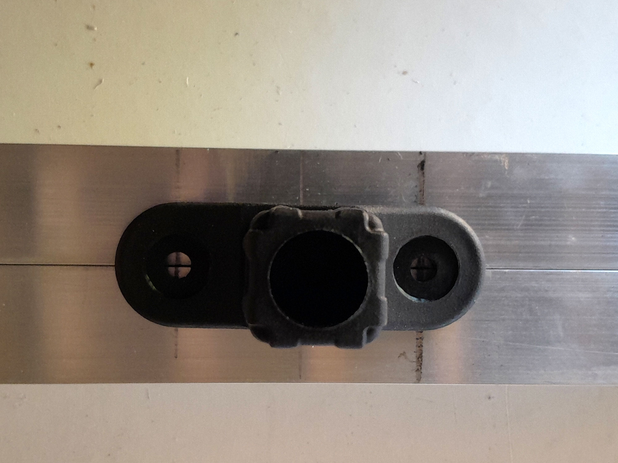
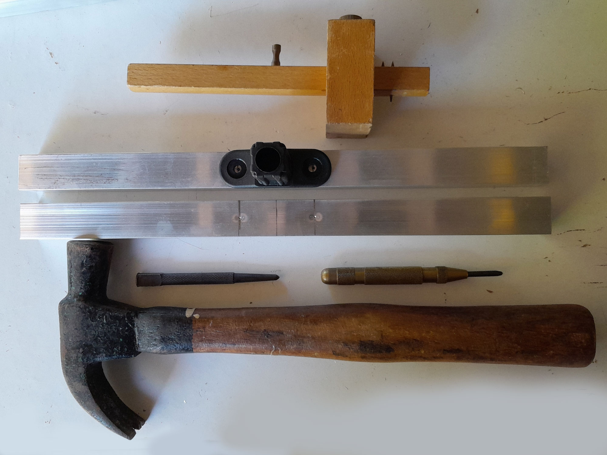
- Having marked (indented) the centre points, I drilled a 4mmØ pilot hole for each securing screw.
- Here you can see they are both precisely aligned with the brace.
- Just before securing the braces in position, and using a piece of scrap aluminium, I confirmed the 4mmØ pilot hole was the correct size.
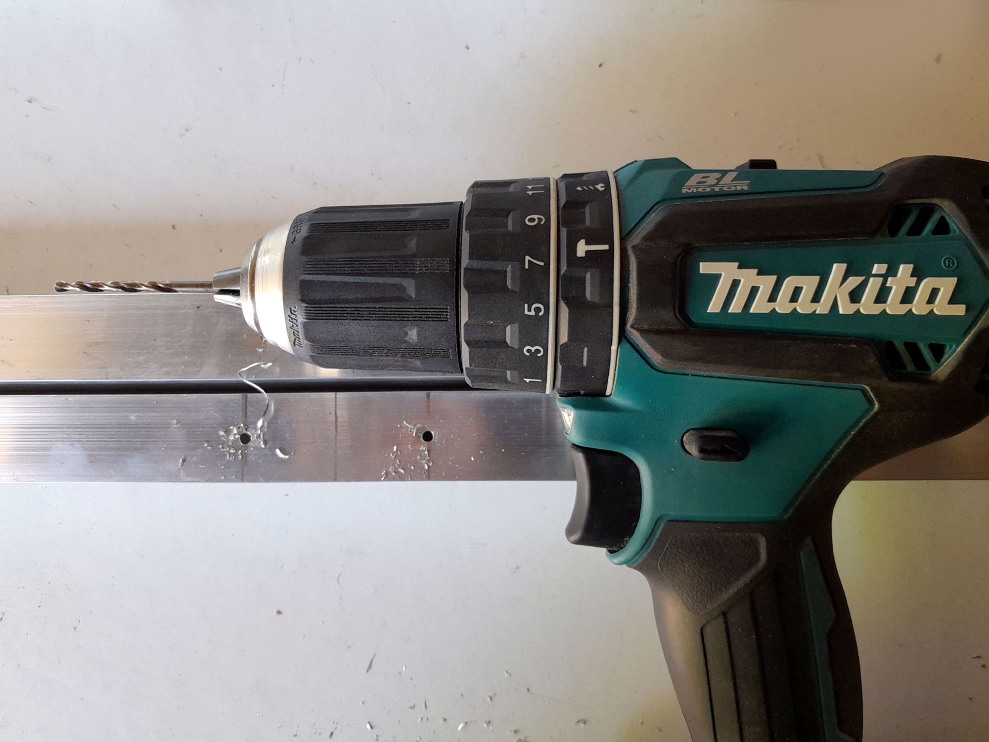
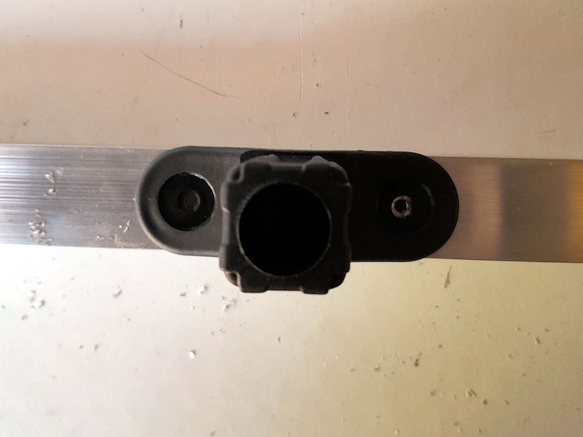
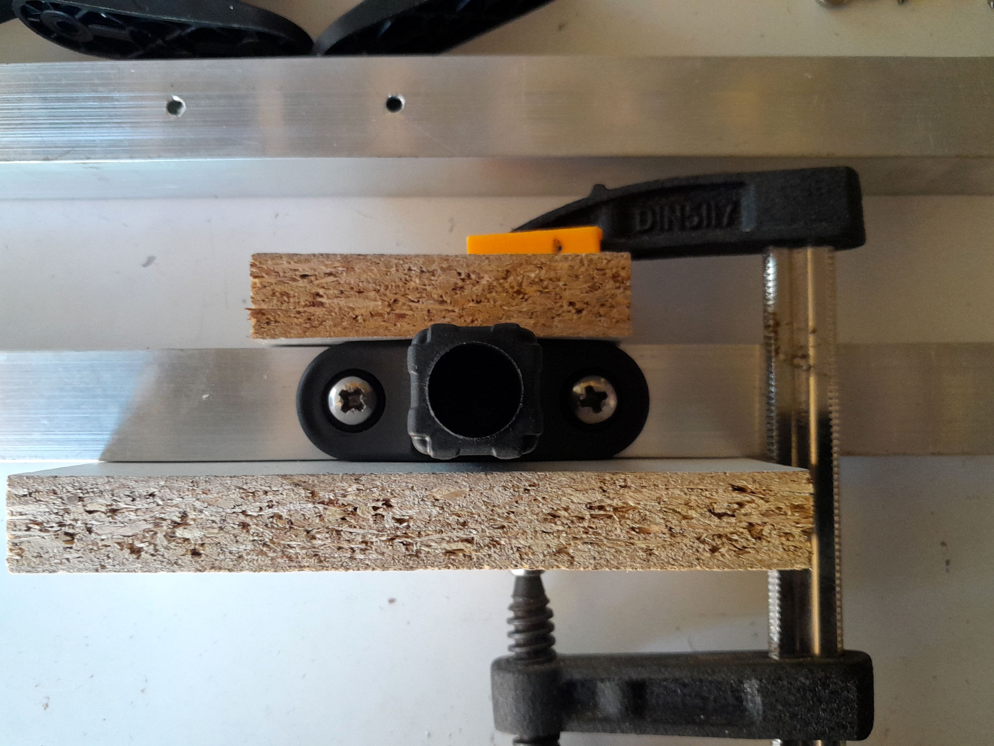
- To ensure that the braces were perfectly aligned, I clamped them on the cross arm and used a couple pieces of scrap chipboard to ensure the brace was perfectly aligned and held securely in that position, and drove in each securing screw.
- Job done!
- Then I used a wooden mallet to seat each T connector. Just make sure that they are properly aligned… believe me it is too easy to fit them and 90º to each other – that’s when you turn the air blue, and neighbours take their children indoors. If that should happen – wrong alignment, not the kids being yanked to safety and out of earshot – you will need to tap the offending connector out and reseat it.
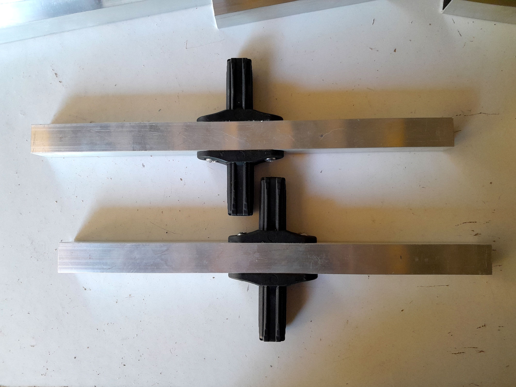
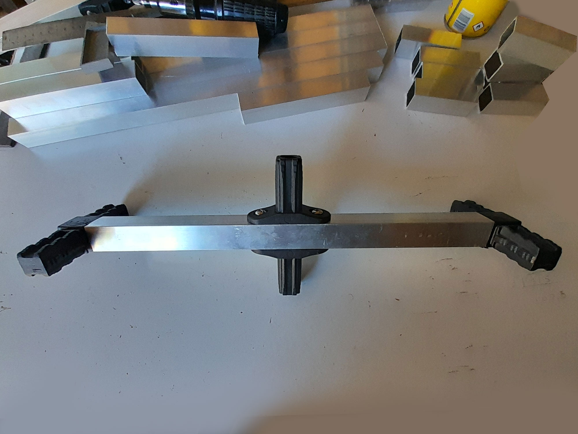
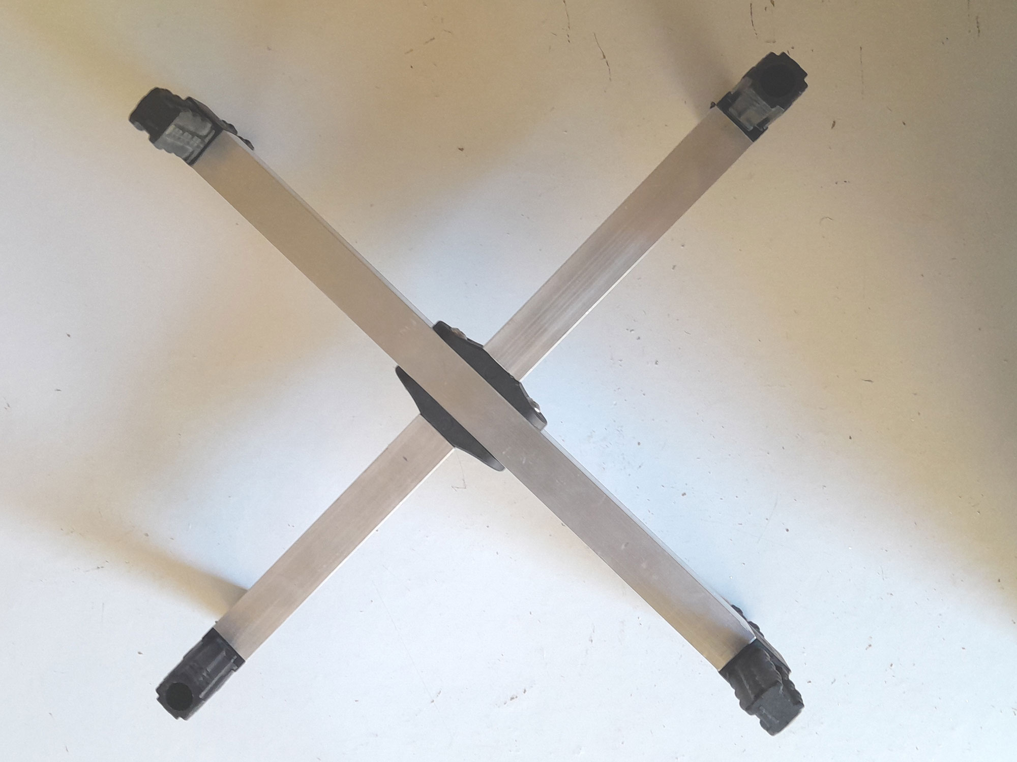
- One of the cross arm assemblies complete… looking rather like a four-prop drone main frame.
- I then completed the assembly and tapped in the end caps. Then I used a utility knife to remove any little bits of the connectors and end caps material shaved off during the seating process. Note: When assembling the stand, if you attach the legs to each cross arm assembly and then seat them, you must ensure that you keep the seating lengths as even as possible, tapping them down in rotation, because if you seat one side completely and its matching mate on the other side is not, you stand the risk of either bending the aluminium and/or causing the connectors to over-flex.
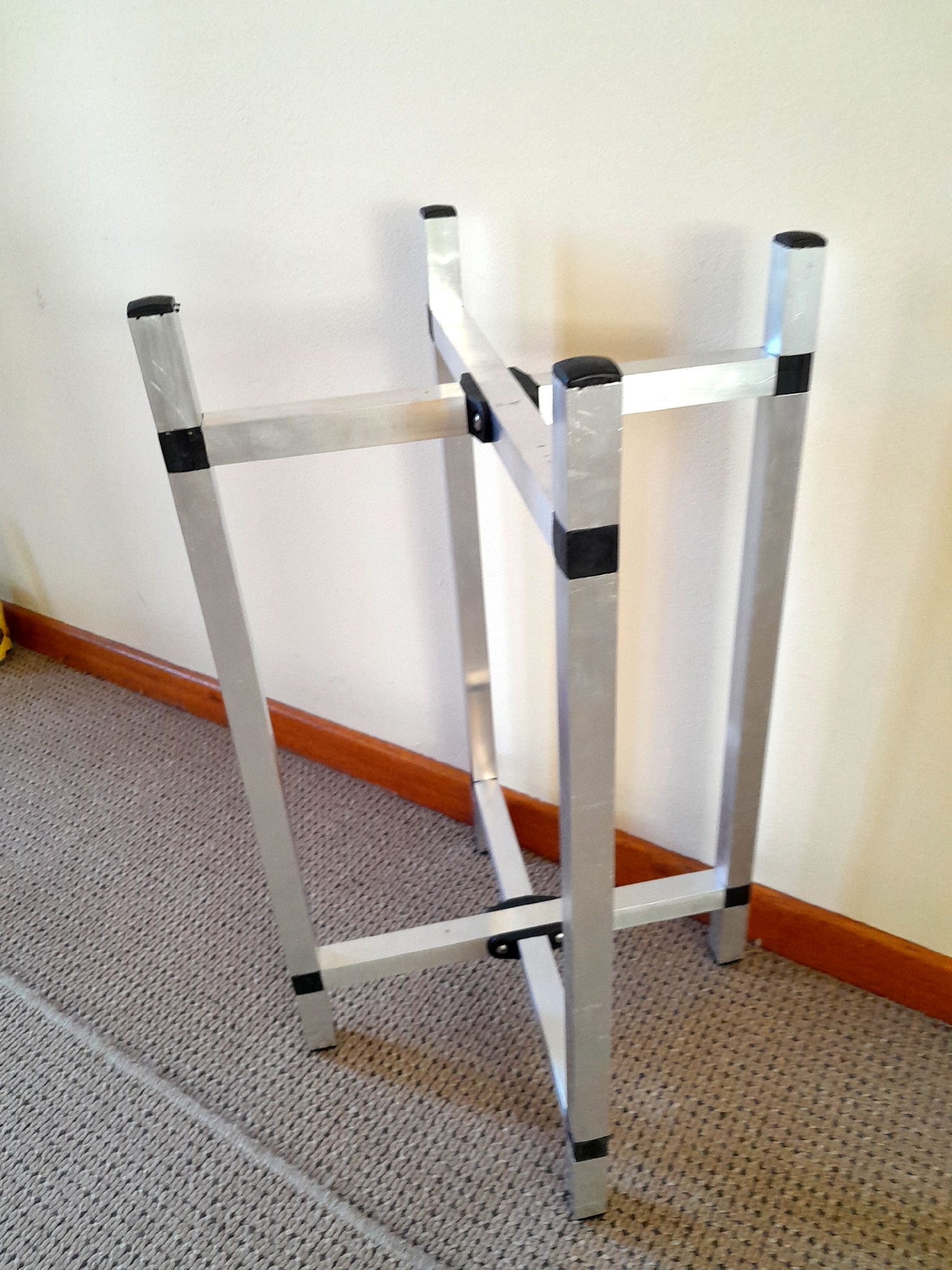
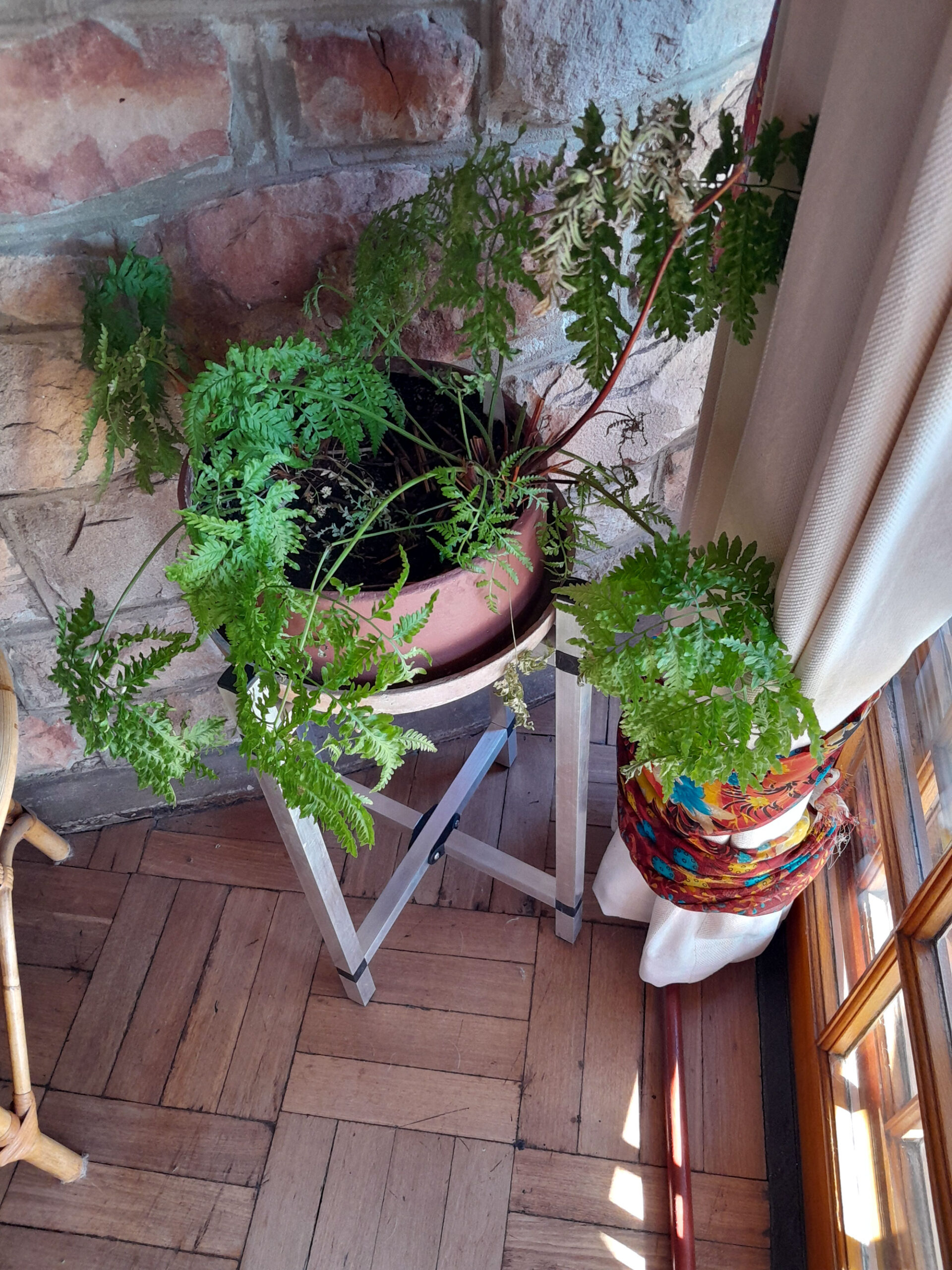
- The completed stand. Here it looks quite utilitarian, but you need to visualise it with a trailing pot plant or one with long fronds draping themselves down it.

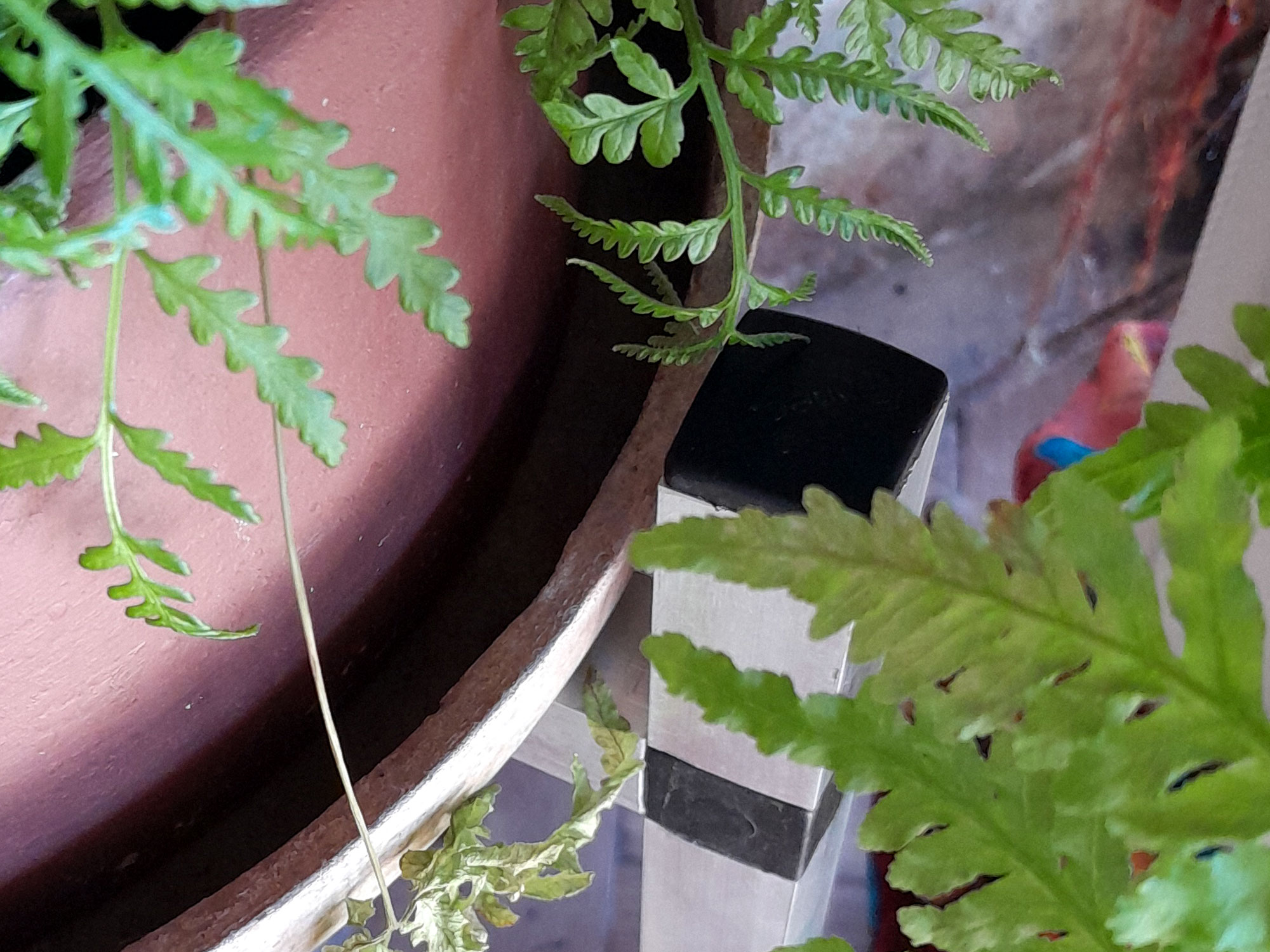
- Here is a close-up of how the tray fits within the stand.
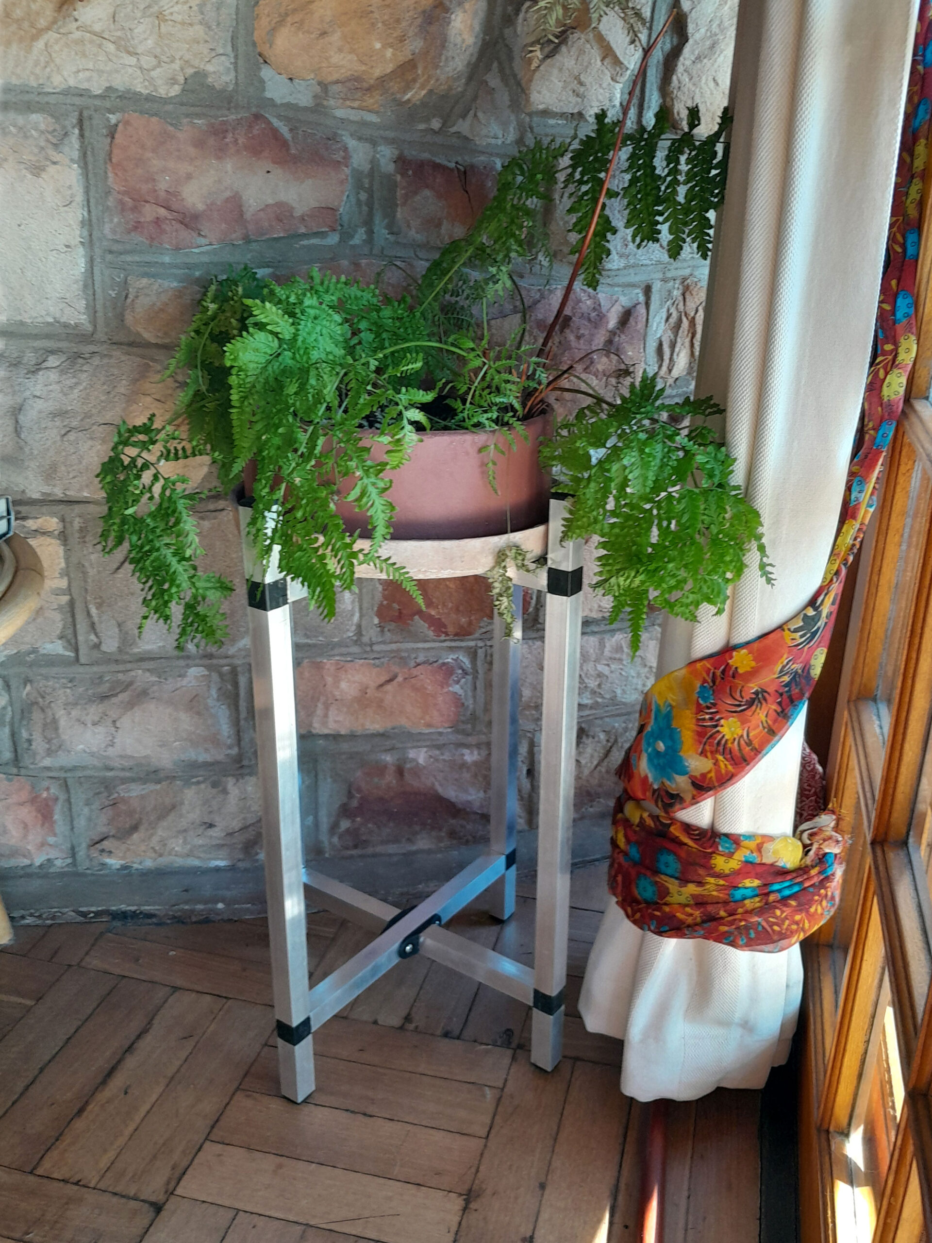
- The completed stand, doing what it is designed to do.
- And another view from the top.
Tools:
Drill/driver (mains or cordless), 4mmØ drill bit, hacksaw, jigsaw fitted with metal-cutting blade, or circular saw/mitre saw fitted with a blade for cutting aluminium, centre punch and hammer, or spring-loaded centre punch, gauge, wooden mallet and/or bar clamp.
Project guide
- Difficulty: Experienced
- Estimated time: about a full day
- Cost: Depends on the cost of the materials from your Mica and the dimensions of the stand, but for the example featured here, about R500
These materials are available at selected Mica Stores, or your local Mica should be able to order them for you, or be able to suggest a supplier. To find your closest Mica and whether or not they stock the items required, please go to www.mica.co.za, find your store and call them.

Celebrating Growth, Achievement and Future Leaders: The 2025 Mica Development Academy Graduation
Every year, Mica Hardware invests in shaping the next generation of industry leaders through its in-house graduate programme, the Mica Development Academy. Since its inception in 2013, the programme has empowered 117 graduates, each walking away with more than just technical expertise — they leave with confidence, purpose and a renewed sense of possibility.
This year, we proudly celebrated 10 outstanding graduates at a special ceremony hosted at Spiro’s Mega Mica. The 2025 programme placed a strong focus on personal development, encouraging participants to grow not only as professionals, but as people. From communication and emotional intelligence to problem-solving and customer care, students strengthened essential life skills that will support them both inside and outside the workplace.
The journey would not have been possible without the dedication of the team behind it. A heartfelt thank you to Lynn Christian, who led the presentation, as well as Duncan Nel, Wallace Brown and Christine Marais for their commitment and passion in bringing this programme to life. We’re also grateful to all the store managers whose ongoing encouragement continues to shape these individuals’ paths.
Congratulations to our 2025 Graduates
Representing our Western Cape stores, we proudly applaud:
- Micheala Samuels – Bracken Mica
- Dirk Beukes – Central Mica
- Cohane Brown – Dick and Allsop Mica
- Zonke Nogemane – Hout Bay Mica
- David Chipinda – Kendal Mica
- Nomthunzi Jane – Millside Mica
- Juanita Nel – Spiro’s Mega Mica
- Busi Yothwana – Spiro’s Mega Mica
- Jonathan Petrus – Spiro’s Mega Mica
- Anathi Mpalala – Spiro’s Mega Mica
Their growth over the course of the programme has been nothing short of inspiring and we couldn’t be prouder of how far they’ve come.
As these graduates step forward into the next chapters of their careers, we know they’ll carry the lessons learnt into every interaction, challenge and opportunity — both at work and in their personal lives.
To the Class of 2025: your determination and enthusiasm show what the future of our industry can be. You’re not just completing a programme — you’re stepping into your potential and helping shape the next era of Mica Hardware.
Here’s to continued learning, meaningful transformation and all the success that lies ahead.
How to fit swimming pool hand rails
First of all, when selecting the rail or rails you require, shop around – as you would usually do for any purchase.
Some rails are designed to have their lower end fixed to a step or the bottom of the pool. Others are designed to be attached to the paved surround. I chose the latter type as the former would have required a lot more work and possibly draining the pool, plus all the hassle of properly sealing it again.
In the case of these rails, we were able to obtain them on a special deal, which included a 25% discount on the second. So the total cost here was just over R6800, for the pair – and that included free shipping from Durban to Cape Town!
The rails are 316 grade stainless steel – which is marine grade (your kitchen stainless steel cutlery and pots etc are often 304 grade) and came complete with the required 10x50mm stainless steel coach screws and plugs.
This was a great deal.
The next step was to install them, so I called around to get some quotes.
Once I had picked my shattered body up off the floor, I decided to do the job myself, as the lowest quote per rail was R1900! Each!
Having said that, unless you are absolutely certain of your skills and ability, even the best rails at the best price are a bit of a thorn in your side if you don’t install them properly – and THEY MUST BE SECURE. So if in doubt, bite the bullet and have them installed.
(Many suppliers offer the rails and install them for you – but that is added to the overall cost, not unnaturally – they are after all, businesses.)
Measure up properly
Your first step is to decide on a position for your rail/s and accurately measure up… more of that in the captions…
But first… a word of caution!
Be extremely careful when positioning the rail/s as you do NOT want to go through any pool plumbing, either the outlet/s or weir inlet. So site them so as to avoid any danger of that.
Also allow for the fact that if you are installing two rails, as here, they need to be spaced about 650-700mm apart. Wider than that can make it more difficult for youngsters to use them, narrower than that, and can cause problems for users who have a “wider girth”, if you get my meaning.
Note:
The slabs used around this pool are about 50mm thick, so coach screws no longer than 60mm are needed; 50mm are fine. Also please note, beware of installing the rails too close to the edge of a slab; even though they are concreted in with concrete grouting between them, you do not want them to crack.
Materials:
- Stainless steel:
- (316 grade) hand rail*
- Six or twelve 10x50mm stainless steel coach screws**
- One pack of 10mm flat washers
- Nylon walls plugs – 6 or 12**
- Epoxy – optional
*Rails are available in stainless steel or chromed, and possibly some contractors offer a galvanised. I went for the top of the line.
**Supplied by the manufacturer, but I purchased the washers and epoxy separately.
Method:
- Our pool is 3×5.5m, with 4 outlets on a semicircular set of steps at the end opposite the weir, so my first step was to use a length of timber to accurately mark the midpoint of the pool on the weir end.
- It pays to be a precise as possible. So I ensured the ends of the timber were overhanging the same distance – to the millimetre.
- Then I measured from the edge of the coping on one side and to the other and the midpoint was 1470mm, which I marked as shown (the coping overhangs the pool sides a little.
- I confirmed that the midpoint was also the middle on the weir. I had already guessed it would be, but I checked anyway.
- Now on the outlet end, I positioned the timber across it, again positioning it carefully to have the same overhand on both ends.
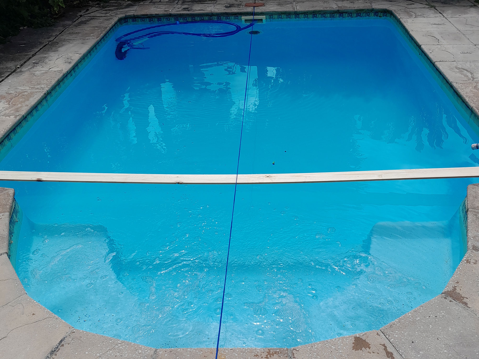
- As you can see, the timber was laid across the straight sides of the pool, so I then had to use a line to line up on the midpoint as marked on the timber.

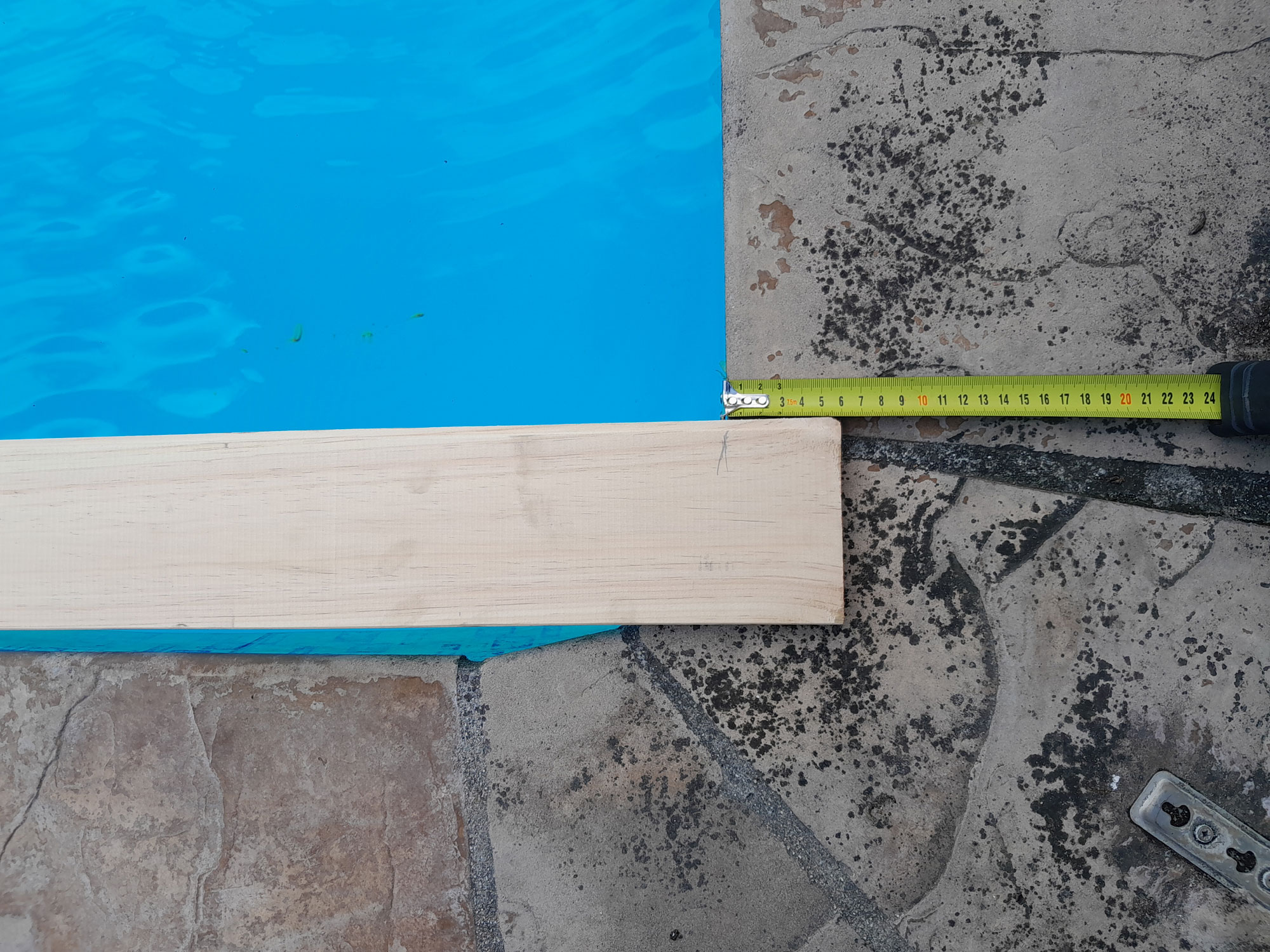
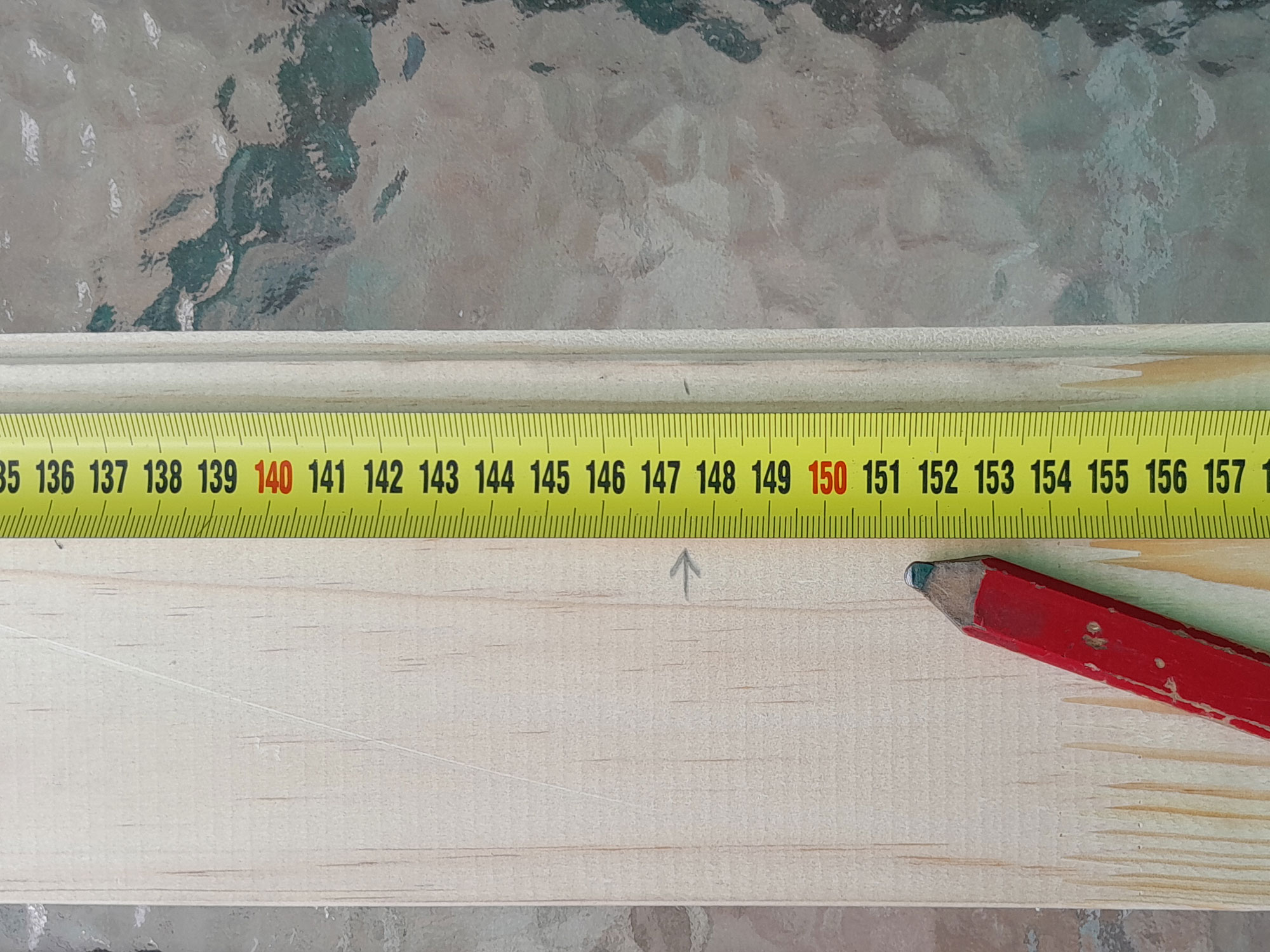
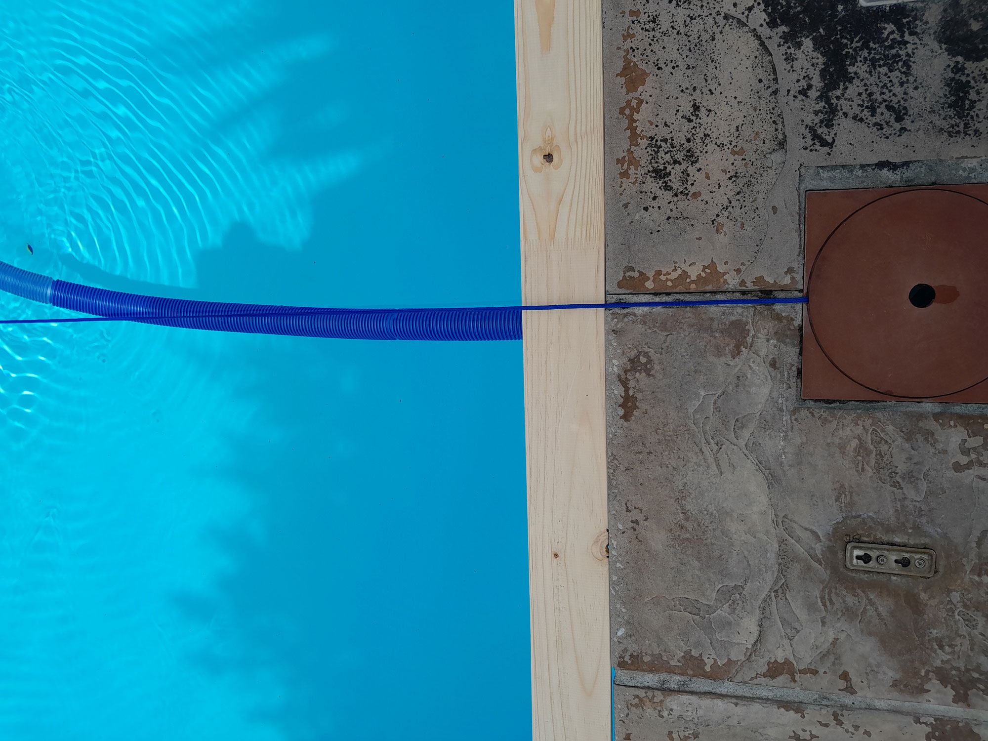
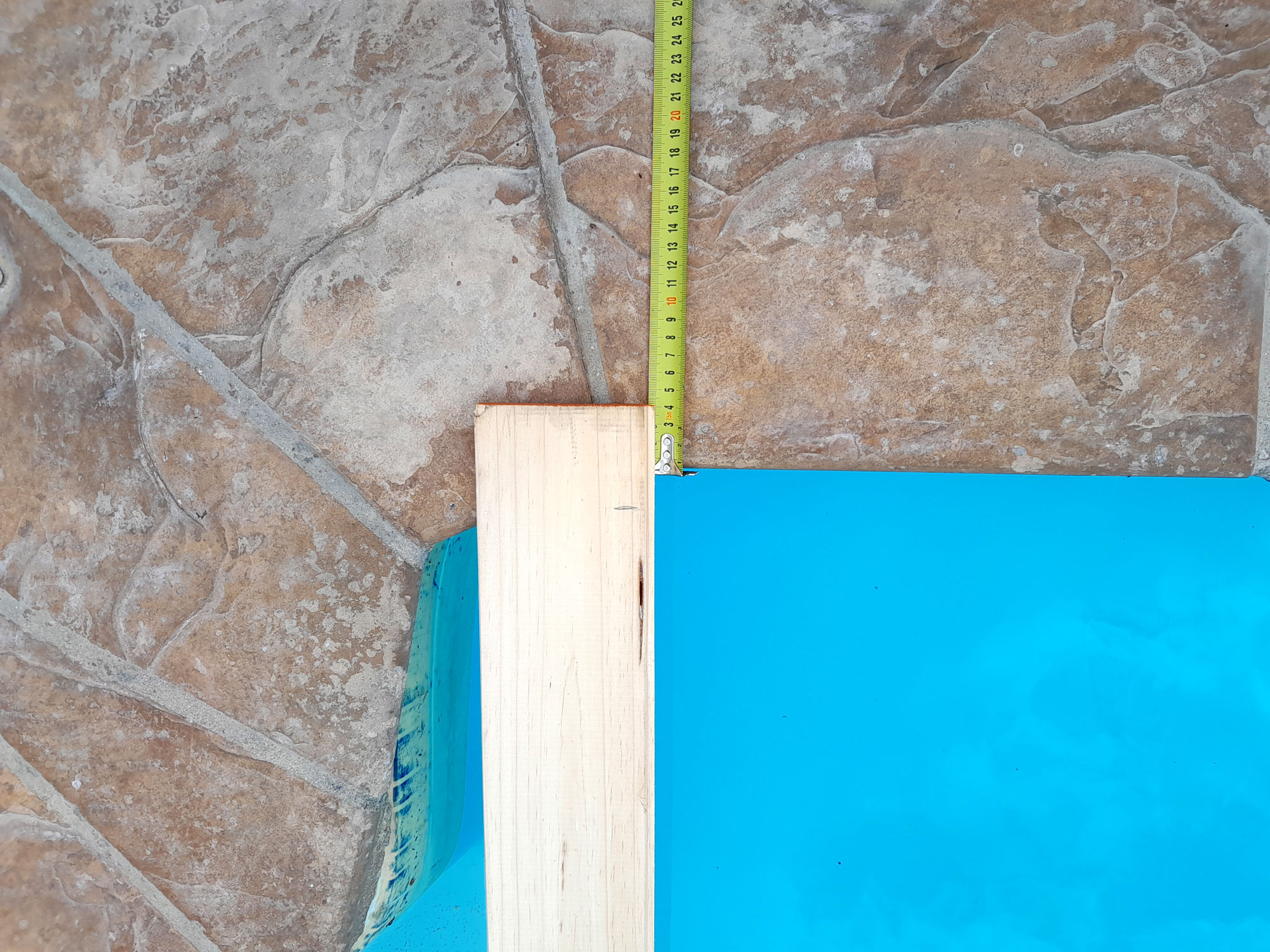
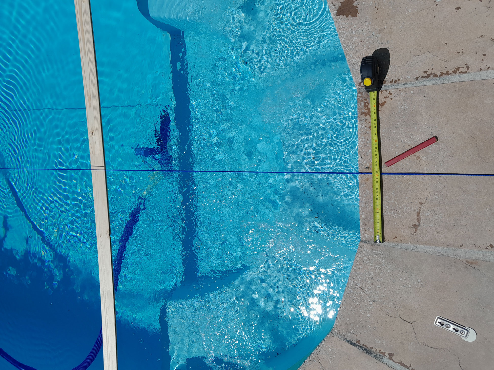
- However, that would then have meant that the centreline would have been offset just 8mm or so from the centreline of the middle slab on the steps. Making that the centreline would thus have resulted in the rails being 8mm offset from the centreline of the slab, and as that would be “right in your face”, very obvious. So I drew a line down the centre of the slab and would align the rails on that. (Come on now, who is going to drag out a measure and say “Oooo… you are 8mm off-centre on your pool 3000mm wide?”!)
- So, here’s the length of STRAIGHT wood used to mark that centreline.
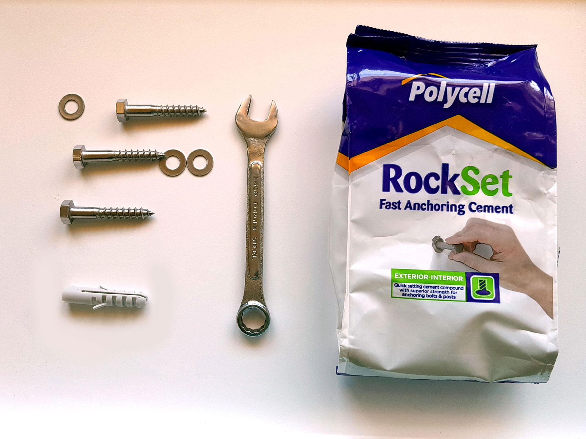
- Here are the supplied fasteners, but I also had a pack of industrial-strength filler on hand for any eventuality
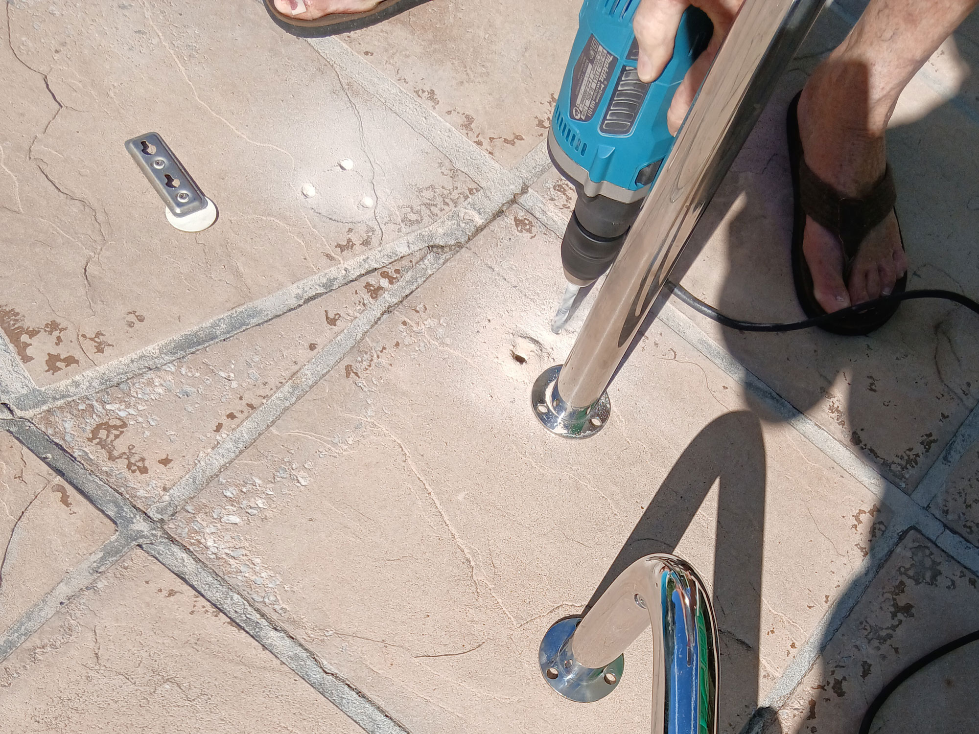
- I drew two lines parallel to the centrelines and 335mm from it, to give a spread between the rails of 670mm… a sort of average between the two suggested extremes. I marked the position of one hole first for the rear base plate, and then drilled it. I lightly fixed the base plate in position, then swung the whole rail around to the required final position, marked and lightly drilled the positions for what would be the front attachment. (You can see the light indentations to the left of the drill.) Then I aligned the rail again, marked off the remaining two holes for the rear attachment plate, and drilled them. Then I completed the holes for the front plate, inserted the plugs and lightly fixed the rail in position.
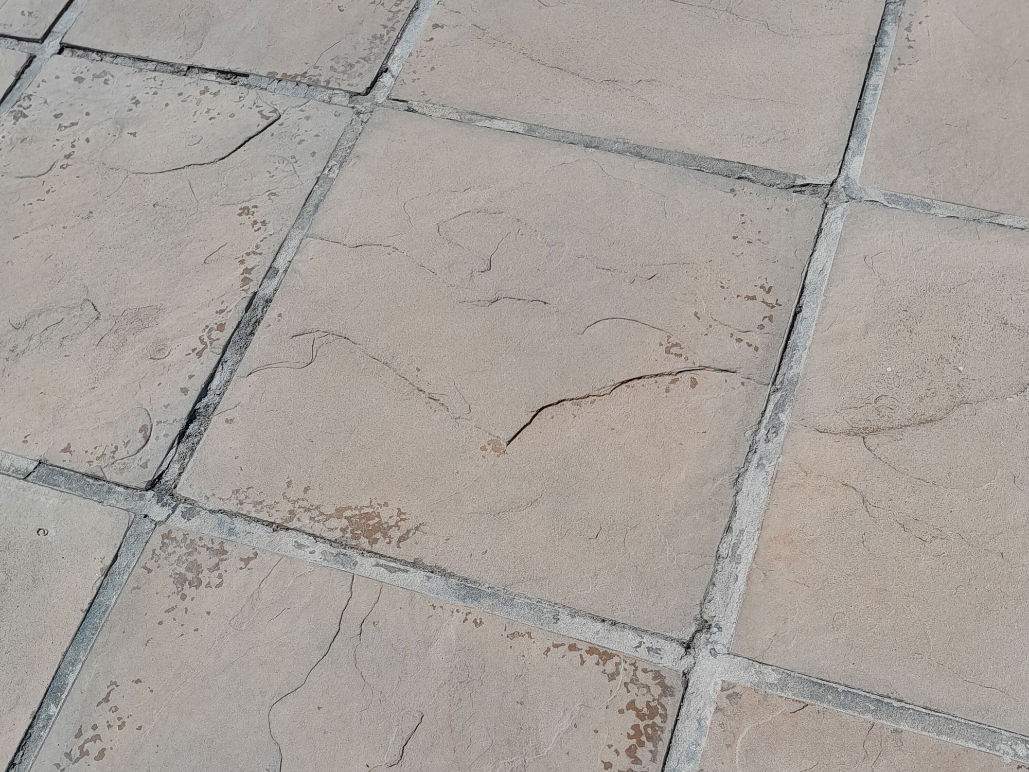
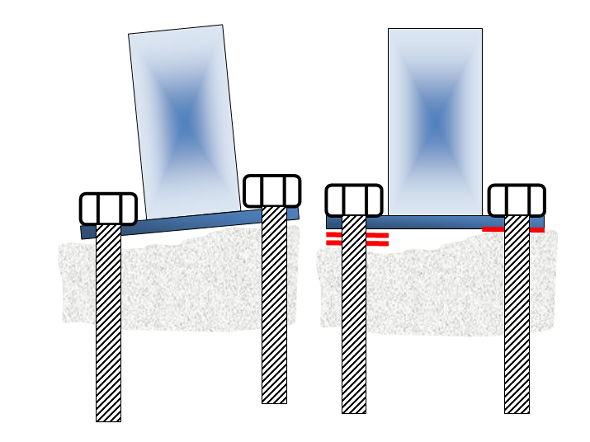
- Note that the slabs used around this pool incorporate a decorative surface, so the surfaces under each base plate are unlikely to be absolutely level or flat. Allied to that, when the slabs were originally laid, they had slight variations in levels. So…
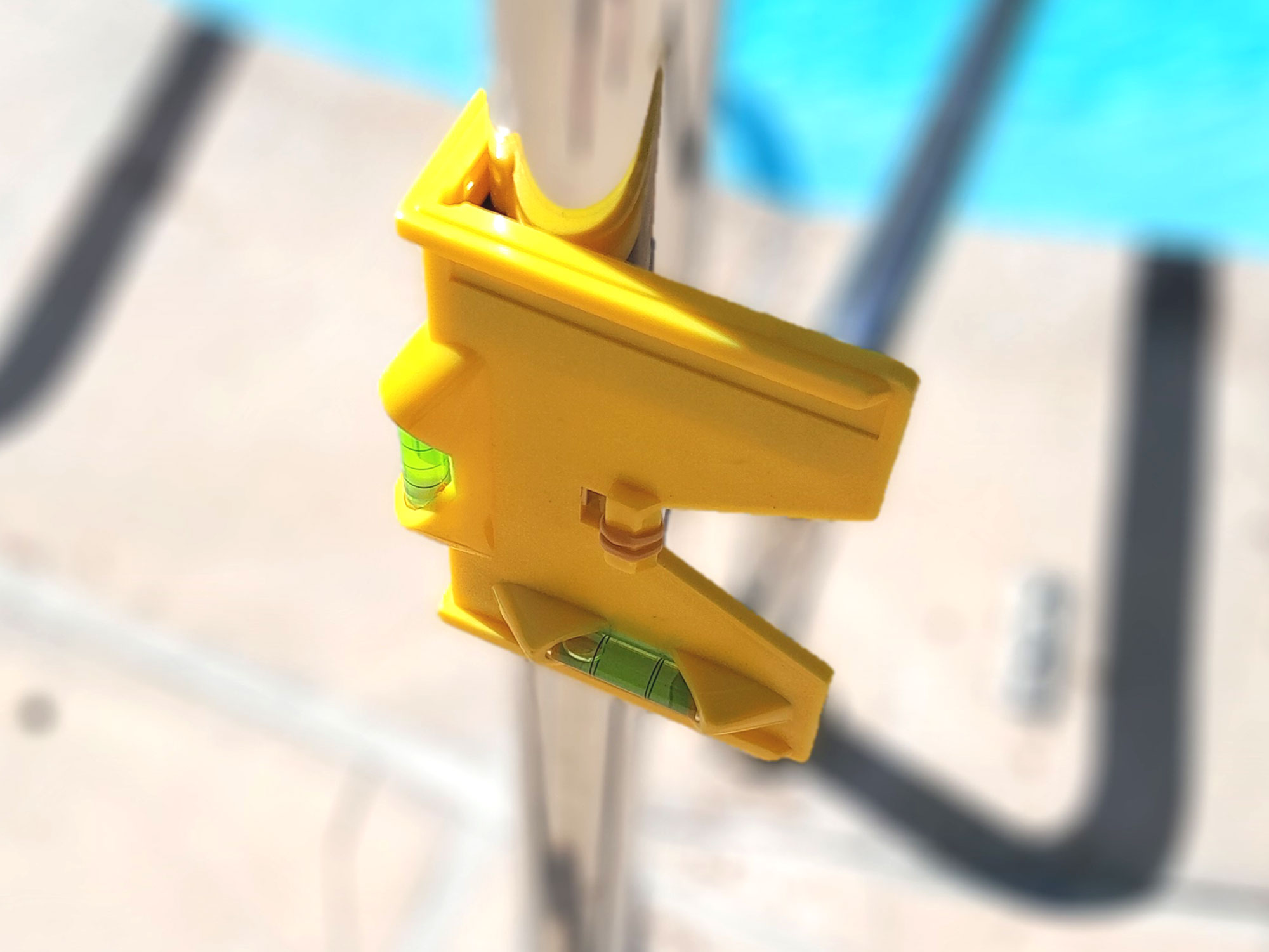
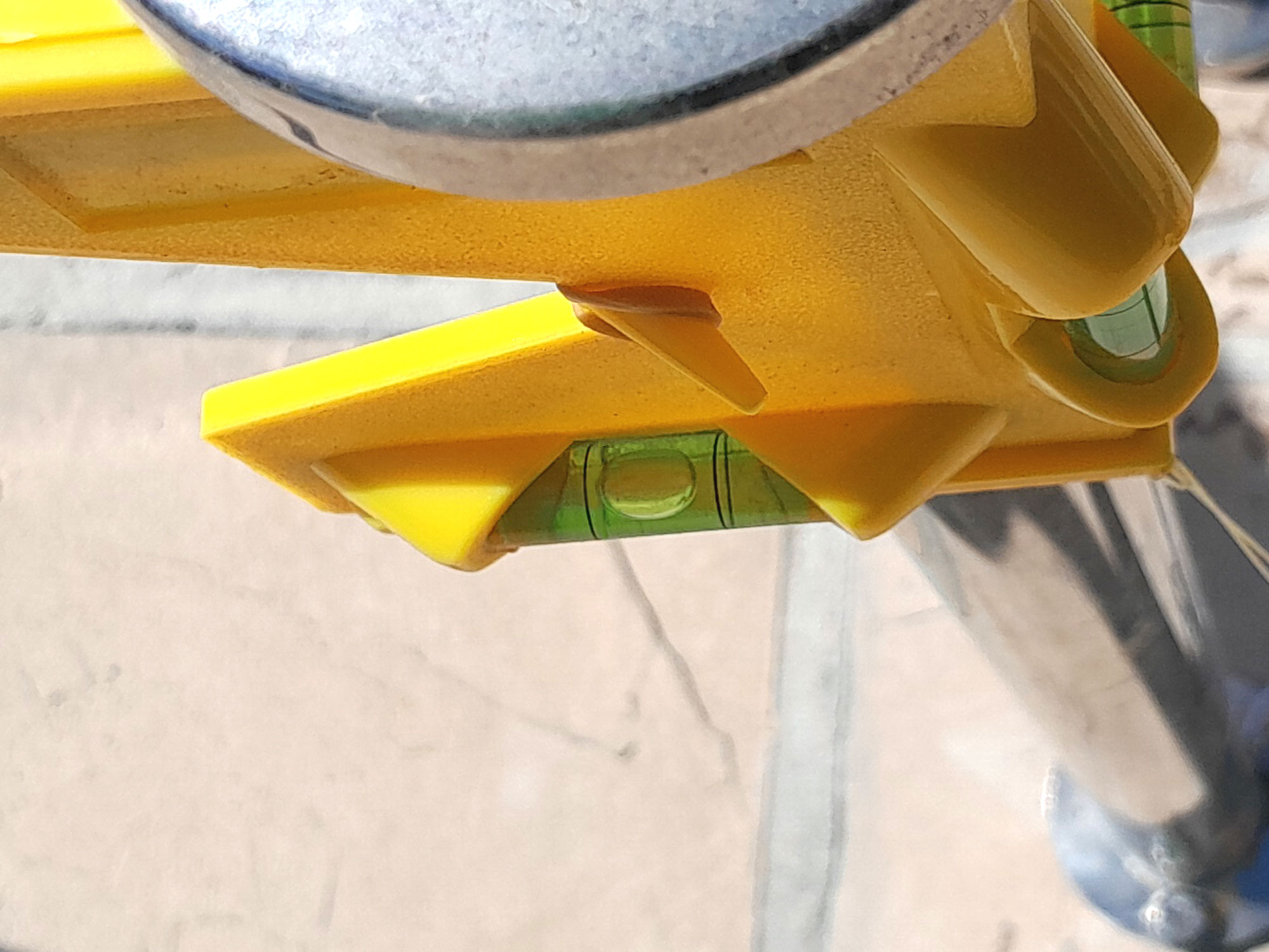
- I used a level as shown to confirm if the rear rail was out of kilter at all… and of course… it was.
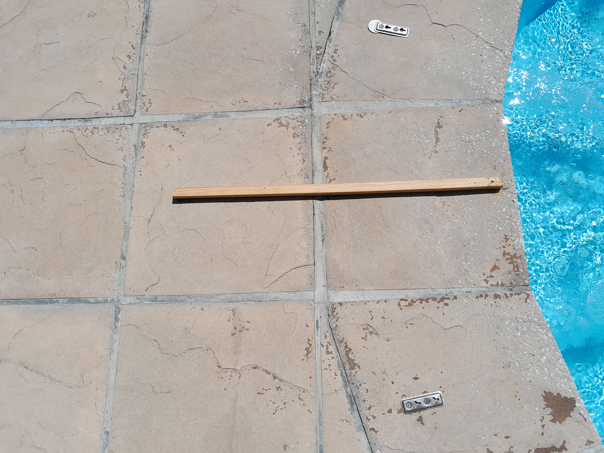
- This shows a VERY exaggerated view of the effect of the uneven surface, compared with the use of shims (washers) as required, to “pack” up the unsupported/lower surface.
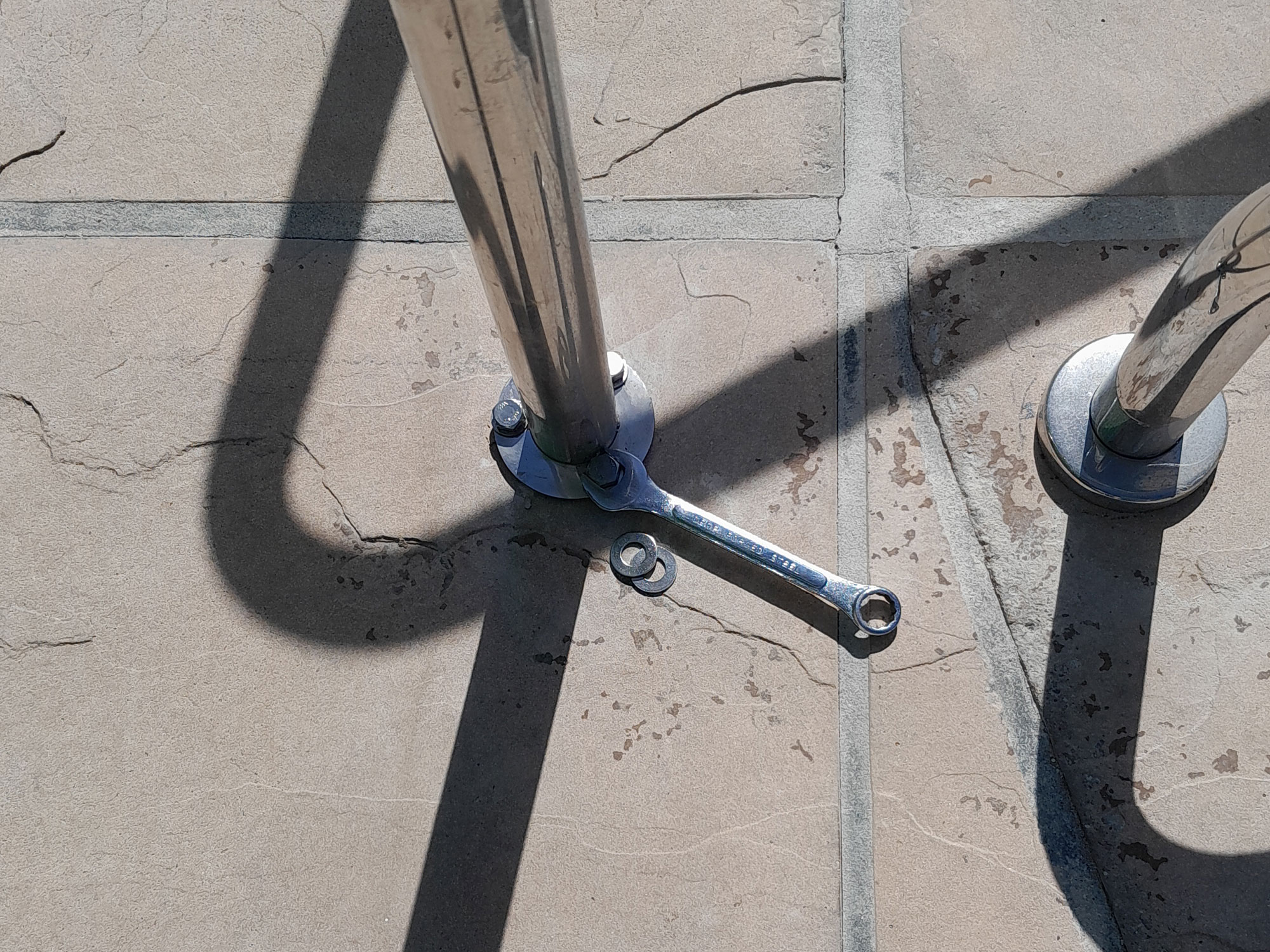
- This shows the shims being inserted under the base plate. It required the complete removal of each coach screw and a little of inserting one, removing another, putting another back in and so on, until…
- Success! Obviously, you must ensure the first rail is very accurately aligned before fitting the second.
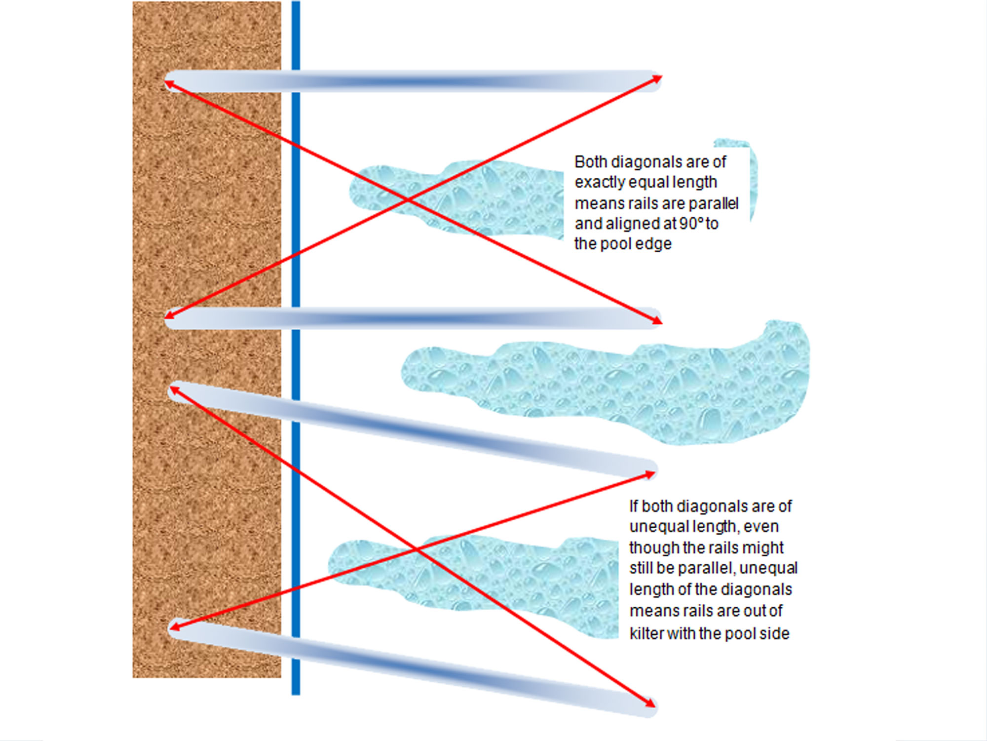
- To position the second rail, I positioned the rear base plate in line with its matching mate on the other side, and used the same method to lightly fix it in place with one lightly attached coach screw. Then I aligned it exactly parallel with the first rail, using equal diagonals to ensure both were parallel and properly orientated towards the pool. Note the lower part of the illustration, which shows that though both rails are parallel, their diagonals for not match and they are both way out. Again, to reiterate… Obviously, you must ensure the first rail is very accurately aligned before fitting the second.
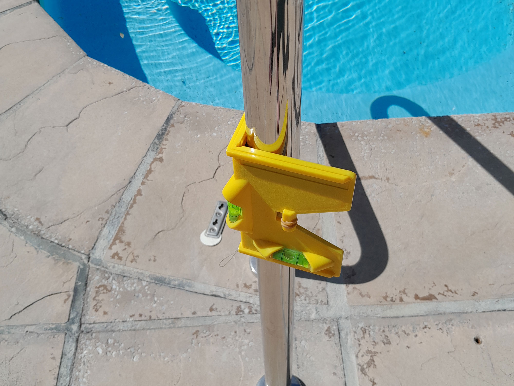
- With the second rail aligned and attached, I checked the rear rail was vertical and thankfully, no shims were required. The decorative covers are preinstalled on the rails and simply drop over the base plats, hiding the bolt heads. A very attractive finish.
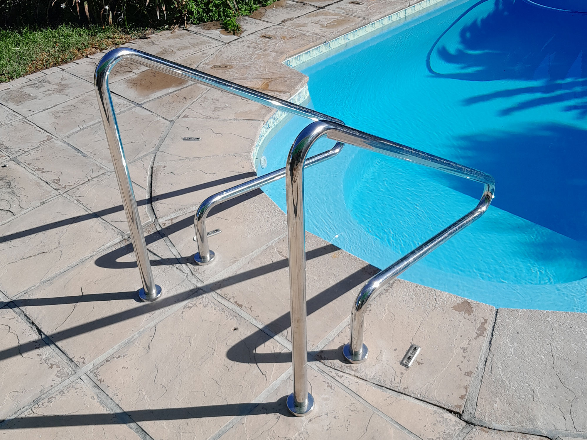
- The completed job… now even this geriatric old coffin-dodger can use the pool again.
Tools:
Hammer drill/driver (mains or cordless), masonry drill bit. This required a 10mmØ bit – to seat the rawl plugs, wooden mallet, and ideally, a ratchet socket set with extenders and a range of socket sizes. The one in question here required a 13mm socket
Project guide
- Difficulty: Experienced
- Estimated time: 1-2 hours, depending on whether you are fitting one rail or two
- Cost: (Depends on the cost of the hand rail/s and its length but can range from a low of R4000 or so, each, or higher, depending on the design and manufacturer
These materials (barring the hand rails themselves, though your local Mica store could possibly order them for you) are available at Selected Mica Stores. To find your closest Mica and whether or not they stock the items required, please go to www.mica.co.za, find your store and call them. If your local Mica does not stock exactly what you need they will be able to order it for you or suggest an alternative product or a reputable source.

How to fit shower hand rails
This is one of two features. This one shows just the simple steps required to fit a safety hand rail, in this case, in a shower. In the other feature we will take an in-depth look at safety rails (also called grab rails)… their sizes, types, designs, materials, types of fasteners, where to fit the handles, how to fit them, and how to avoid the nastiness that comes from drilling though a water pipe or electrical conduit when drilling the holes to fit one.
Materials:
- Stainless steel (304 grade*) 300mm hand rail
- 6x40mm stainless steel screws** – 12
- Nylon walls plugs – 12
*Stainless steel is available in a range of grades, such as 316 – used in marine environments, for example, and 304, the grade used in this instance. 304 grade stainless steel is the same grade often used for stainless steel cutlery and cooking utensils.
** Even if you fit chromed, plastic or mild steel handles, it is a very good idea to use stainless steel fasteners to attach them. Should you even have to remove or change them, the fasteners should still be in fine shape. Using mild steel fasteners will almost certainly see them rust. Not only can that result in unsightly stains down the tile surface below them, but when it comes to removing them they may have rusted beyond redemption – or removing.
Method:
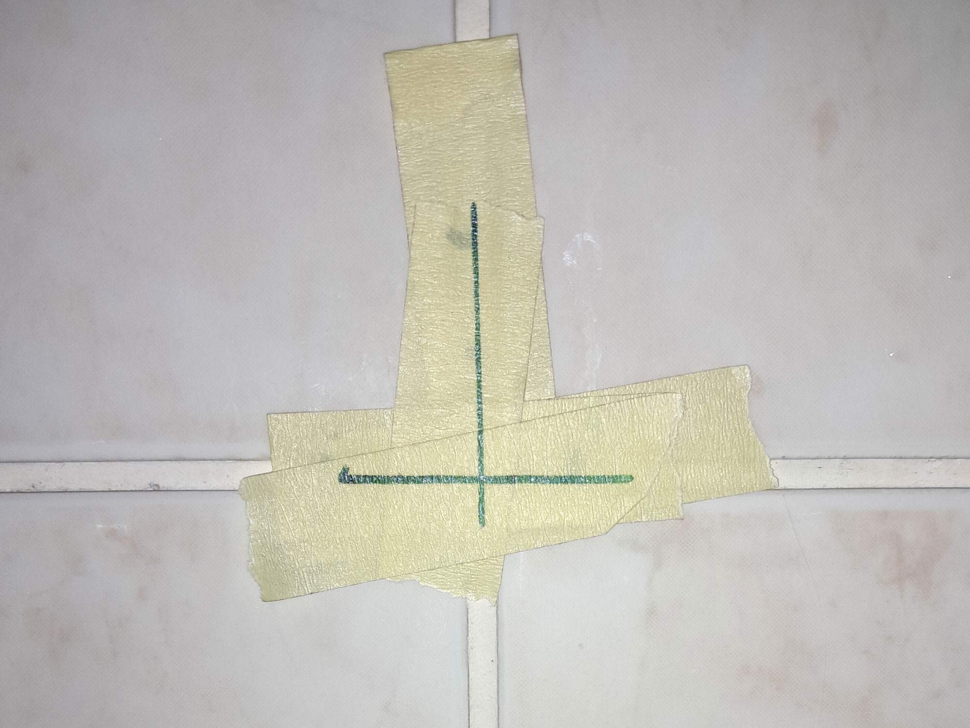
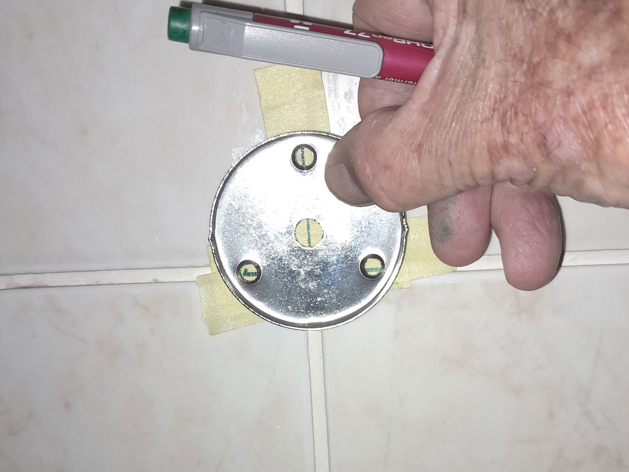
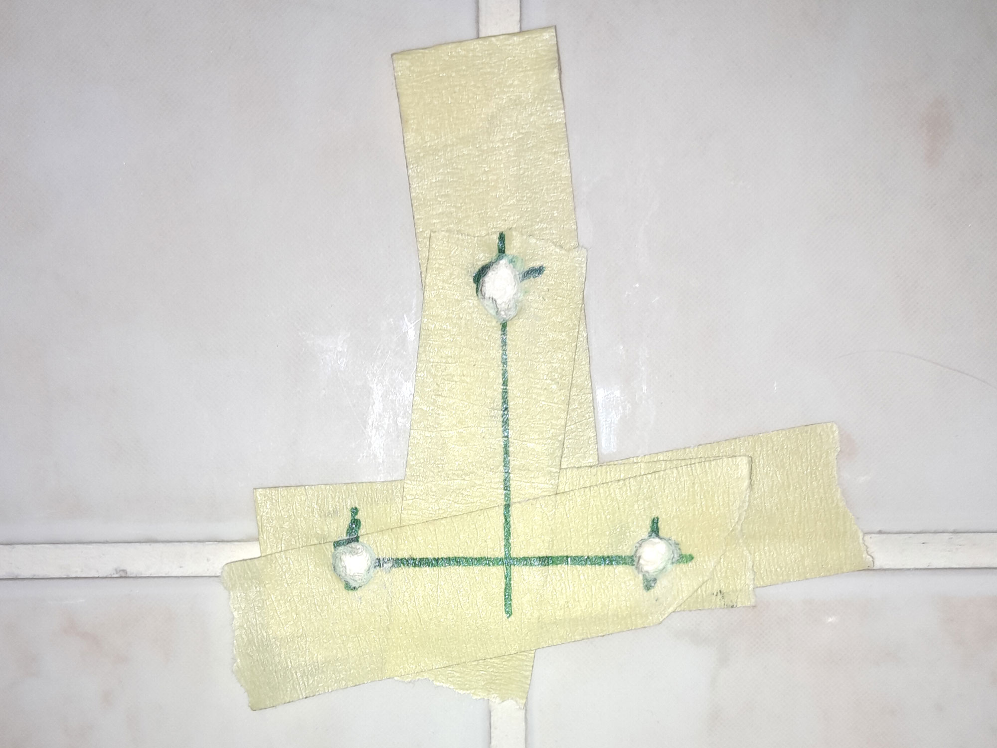
- Whenever it’s possible, when drilling holes in a tiled wall or surface, I drill into the grouting between the tiles. The reason is simple… should I ever need to replace a fitting, or remove it completely, filling holes between the tiles with grout means that they are not as obvious as holes drilled through a tile and then filled. So, first step is to mark the mid lines of the grouting at the junction between four tiles. I used masking tape and a marker pen, as shown here.
- Then I removed the handle’s base plate, held it against the wall with the screw hole positions centred on the lines I had drawn.
- Then I marked the positions of the screw holes.
- You will often use a hammer drill to drill into a brick wall, but while you can use the hammer function from the get-go on plain masonry wall, don’t do so when drilling though tiles. Set the drill function to drill, as shown here.
- Then I fitted a small (3mmØ) masonry bit to drill the starters for the holes. Using a small bit like this allows you to be very accurate in positioning the bit.

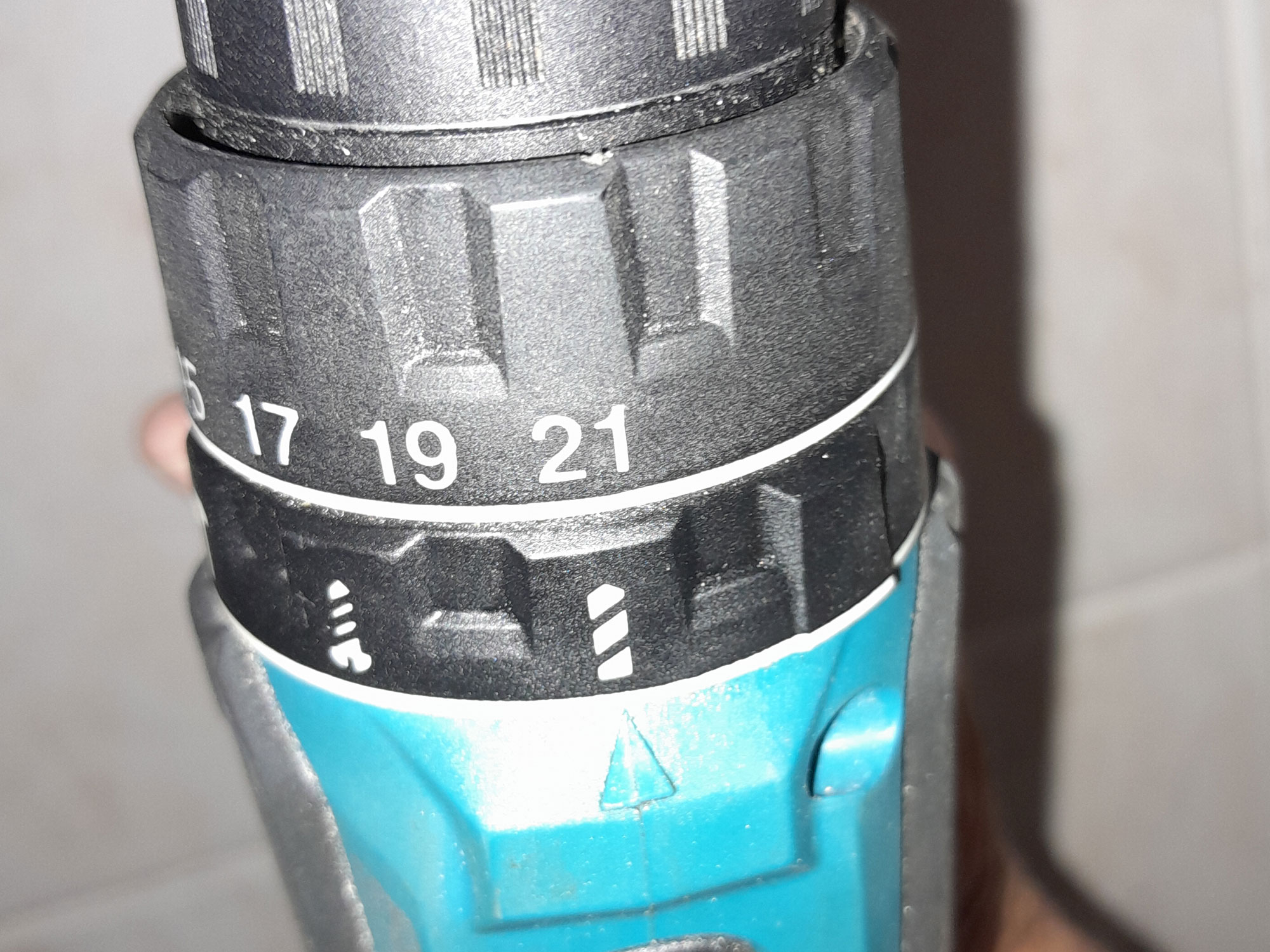
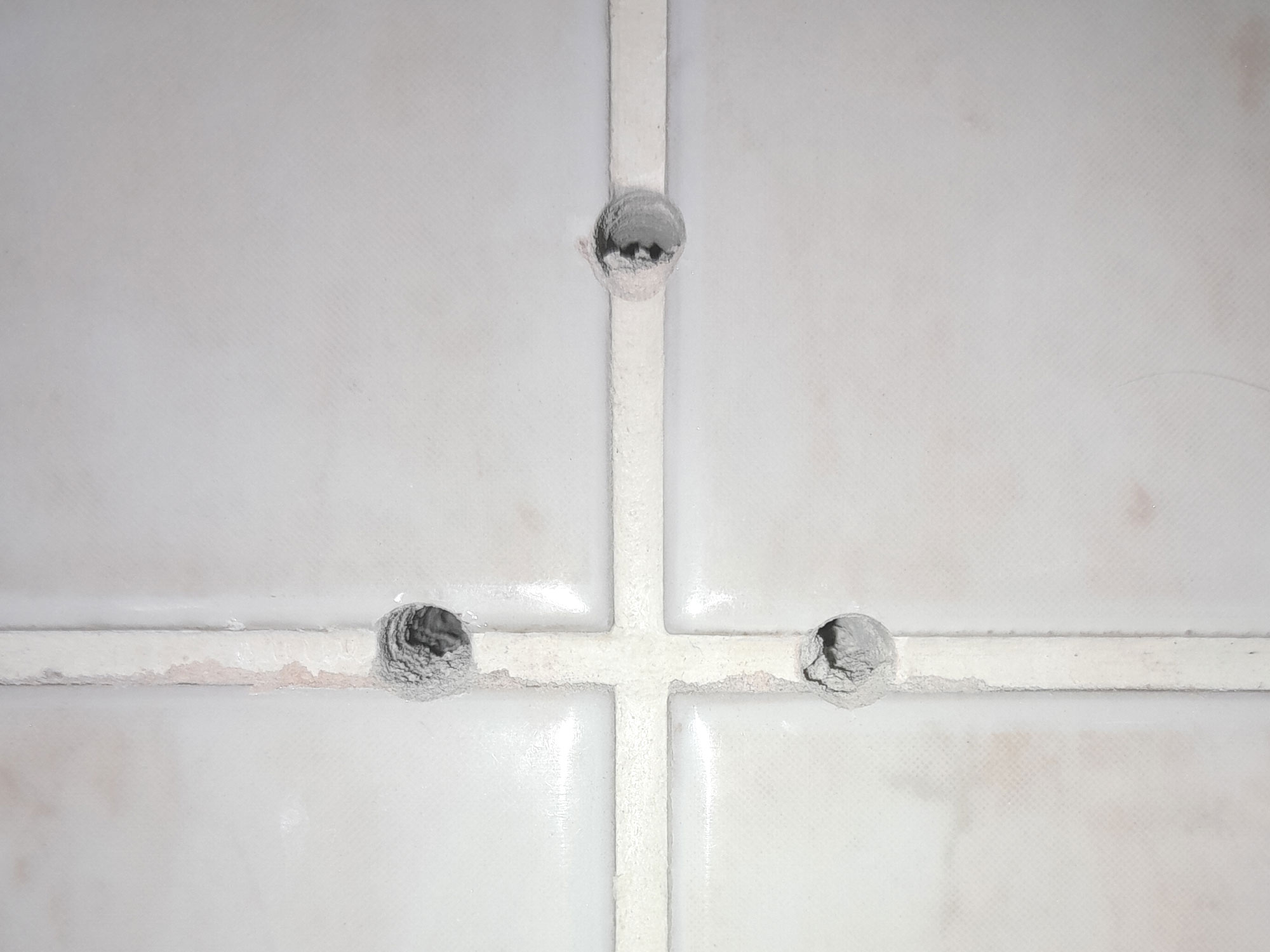
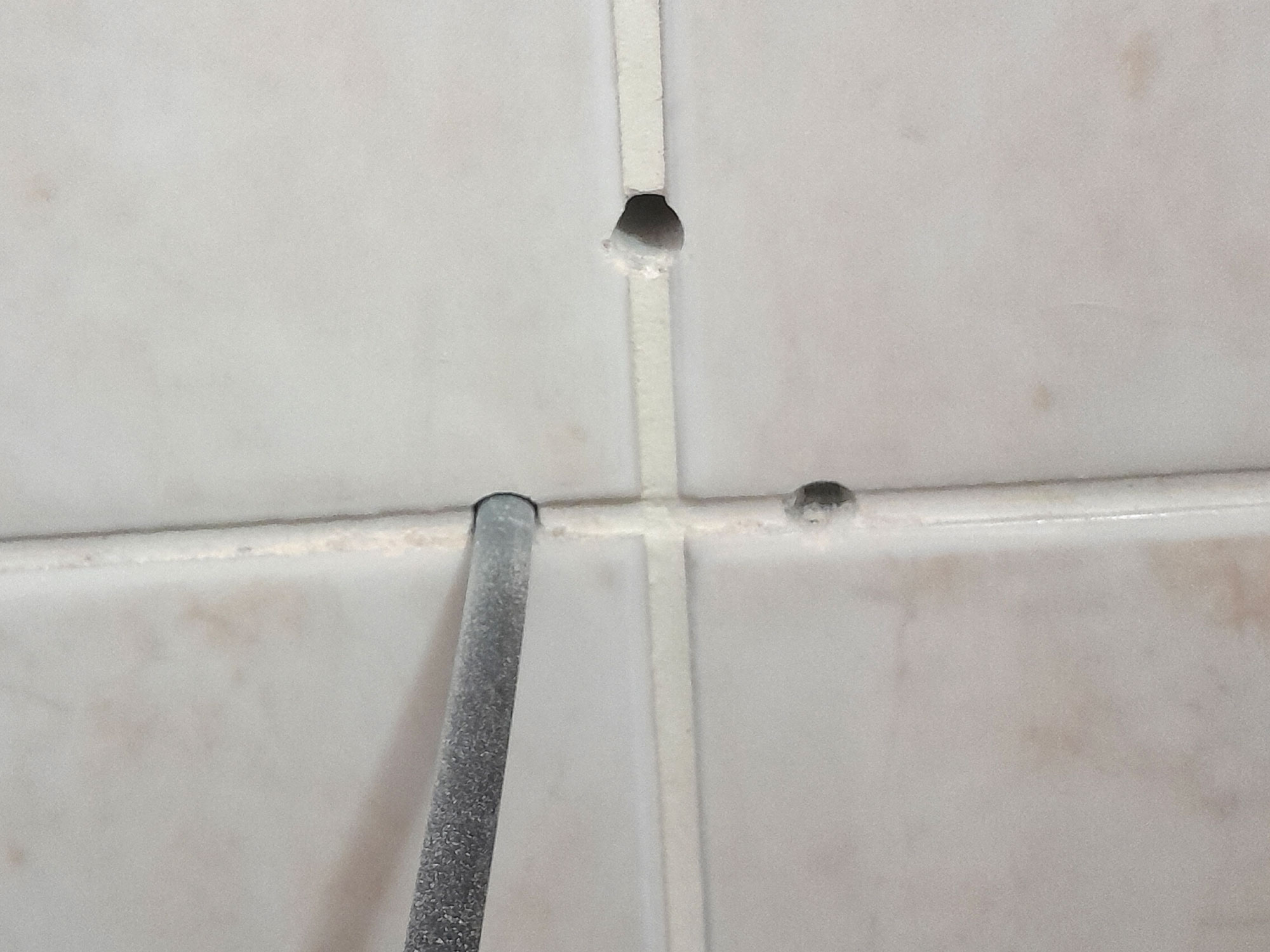
- Then I switched to the full-size 8mmØ bit required to fit the wall plugs, drilled into the starter holes, and only once through the tiles (one can feel a slight “give” when through the tile and on the wall’s surface), did I switch to the hammer action, and completed the holes – as shown here. As you can see, they are full of debris.
- The solution… slide a length of plastic tube fully into each hole in turn, stand to one side (so you are not directly in front of it), and blow. The hole will be cleared. And because you stood to one side, you didn’t get a face full of masonry dust. It’s basically the same principle when you’re on as yacht and feeling queasy … go to the leeward side of the boat, NOT the windward (the direction from which the wind is blowing). Fail to do that and you could get your own back!
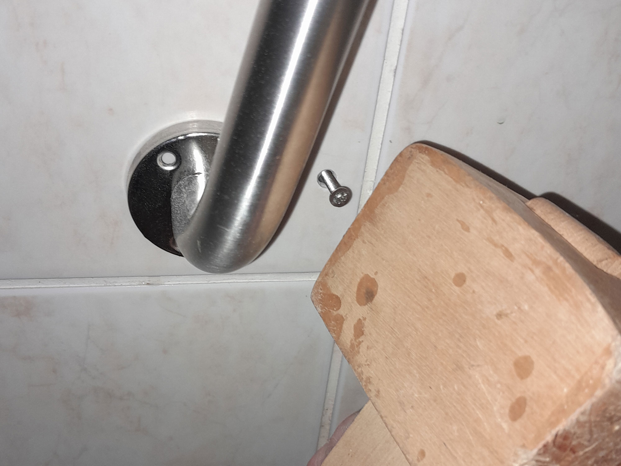
- This shows the lower attachment of the handle, but the point here is… when tapping the wall plugs into their holes, sometimes using the screw as shown here to fully seat it, use a wooden mallet. Don’t use an ordinary hammer… if you miss the plug, or overdo your swing, you will very likely crack a tile or two; the mallet, being wood, is much softer and much less likely to do any damage. HINT: If you do not have a mallet available, then use a short length of dowel, held against the plug or screw head, and tap the other end with your hammer. That should do the job without any damage, because the dowel, being wood, is friendlier to the brittle tile.
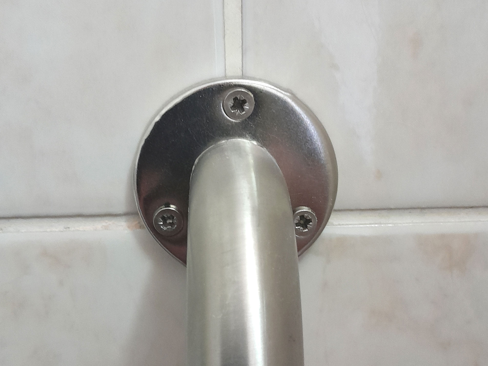
- Back to the top attachment… here the three attachment screws have been driven home, ready to have the cover plate slipped over the base plate.
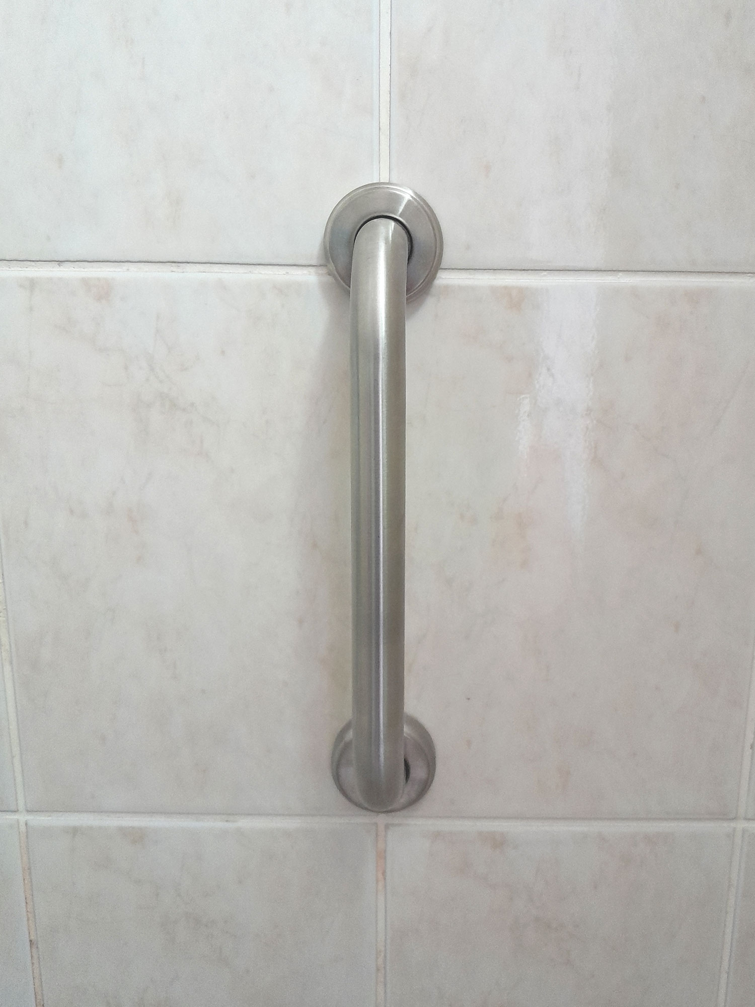
- Job done! And even if I say so myself, looking neat – and making the shower that much safer to use.
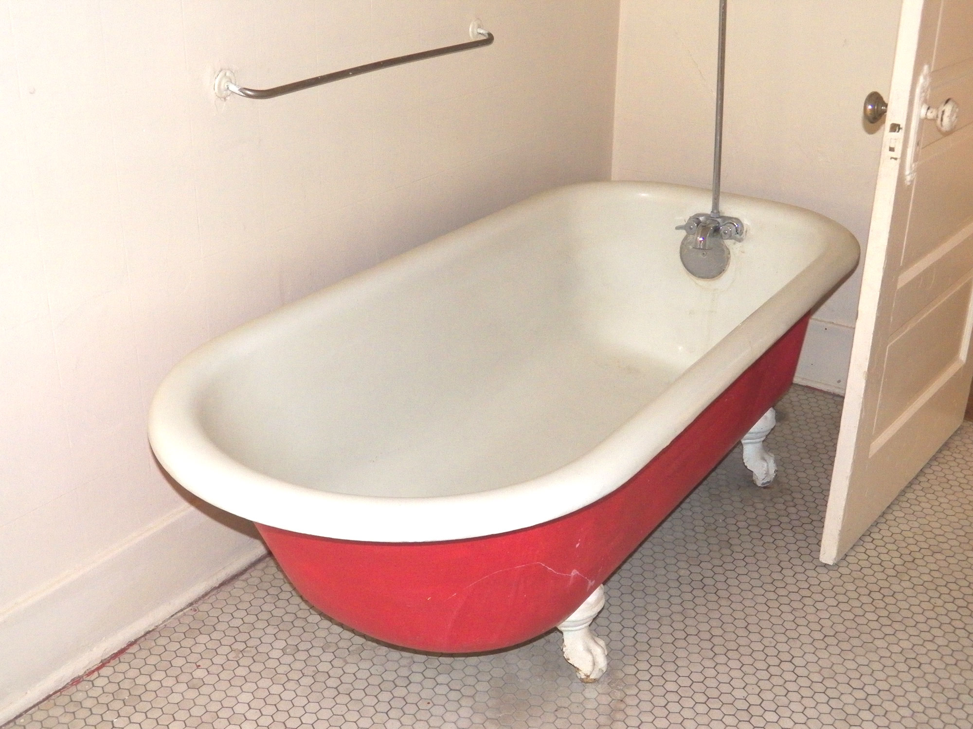
- In passing, here is an example of another safety rail, this time fitted horizontally above a bath. When standing it can be used to steady oneself, and when getting into or out of the bath, a handy handle on which to help the occupant get into or out of it.
Tools:
Hammer drill/driver (mains or cordless), masonry drill bits – one smaller than the other required to seat the rawl plugs, and then the full-size bit itself, wooden mallet
Project guide
- Difficulty: Beginner/Novice
- Estimated time: 1 hour
- Cost: (Depends on the cost of the hand rail and its length but can range from a low of R350 or so, up to R100 for the longest versions, and also whether or not they are stainless steel [recommended for installation in bathrooms and showers])
These materials are available at Selected Mica Stores. To find your closest Mica and whether or not they stock the items required, please go to www.mica.co.za, find your store and call them. If your local Mica does not stock exactly what you need they will be able to order it for you or suggest an alternative product or a reputable source.

Let’s go-go… gazebo
The first point is this – what is the difference between a gazebo, and a pergola?
The difference is that gazebos incorporate a waterproof roof, whereas the roof on a pergola is very often open, but with beams running across it to allow for creepers and suchlike to eventually provide shade. So the roof is not waterproof, and whatever is under it will still get wet when it rains. This means, in passing, that if you opt for a pergola, whatever garden furniture you have in it, will be far more subject to the elements than would the furniture under a waterproof roof structure. In short, the pergola’s roof is intended more to provide shade than protection from wet weather. An advantage of an open roof on a pergola is that it can give an impression of more space, more airiness, whereas a gazebo solid roof can tend to be cosier.
Another major difference is that while pergolas tend to be square or rectangular, gazebos are often hexagonal.
Where to put it?
Before you get too far into the weeds, you need to have a very good idea of where you will put your gazebo, what space is available for it, and hence its size.
There are many questions to consider when deciding on where to put it, and we cover them below, so read on…
Gazebo roofing materials
There is a very wide range of roofing materials available but if you are going for a gazebo, particularly a hexagonal one, and doing it yourself, have your roof panels cut at the factory for you. It should go without saying, however, that once it’s cut, it’s yours, so you must ensure that your cutting instructions are absolutely correct.
Possible options for roofing materials include asphalt shingle, chromadek, concrete ( very unlikely to be used on a gazebo), metal (such as galvanised steel or aluminium), thatch, clay tile, concrete tiles, corrugated iron, slate, polycarbonate or shake shingles
Roofing profiles can include IBR (inverted box rib), corrugated or other profiles – such as simulated tiles.
Gazebo floors
Whereas many pergolas are built over an existing area of paving, such as a patio, or another surface such as a deck, patio, or pavers, a gazebo is more likely to have a dedicated floor, built to fit the floor plan, and quite often, raised, so entering the gazebo is by means of a step or two.
That means a gazebo floor is very likely – if the design calls for a raised suspended floor, as above – will be wood, and built on a series of beams laid at 90º to the floor planks, which are in turn mounted on short pillars. Alternatively, the beams might be attached to the tall pillars making up the sides of the gazebo.
If the floor is a raised type, and you are using paving, then that itself should be seated on a fully compacted raised foundation bed.
Durability
It’s all down to the materials you use. If you stint on the materials, you may well find that in years to come, you will be facing replacement costs for the roof, for example.
So the key is – as always – without breaking your budget, use the best materials you can. This is particularly so in coastal areas, where conditions are ideal for rust and corrosion to attack metal components such as fasteners and brackets, and other materials used in gazebo’s construction… a roof made from mild steel materials such as galvanised corrugated roof panels. Galvanising provide good protection, but it is a wasting process, and wherever the galvanised coating is compromised – such as on cut ends, or fastener holes – rust can start, and eventually you can end up with a roof that looks like a sieve.
Another very important factor to consider is the weather in your area… if it is often subject to high winds, you must ensure that whatever you erect with be anchored securely enough to handle even the strongest of gusts, and also not tear apart.
Costs
Depending on their size and other factors such as materials you use, pergolas are generally cheaper to build than gazebos, as the structure is generally pretty simple and straightforward.
It follows, therefore, that gazebos are the more expensive of the two – again given size, design, and materials.
Hence the simple answer to “What will it cost?” is “How long is a piece of string?”
If you are doing it yourself, draw up your design, carefully list all the materials you will need – from floor to roof, including all your foundation materials, fasteners, brackets and so on, and cost them.
Alternatively, there are many companies supplying, and very likely also erecting permanent structures, and they are well worth considering.
If you are going this route, then the usual advice holds for project you are considering being done by a contractor:
- Ask around social media groups if anyone has had a gazebo built for them, and ask to visit and ask a few questions, such as professionalism, reliability, standard of workmanship, materials, durability, and overall impression of the final result
- Shop around… check websites, ask at your local Mica for contacts to reputable contractors
- Select three or so potentials
- Ask to see examples of their work, but bear in mind that they might tend to give you examples only of those customers they know are satisfied
- Make sure you get a fully itemised, detailed quote from each potential contractor… all materials, labour, permits (if any required by your local authority), and so on
- When paying, pay a portion, usually 30-50%, and only the remainder when you are fully satisfied with the completed result.
(Many retailers offer light collapsible gazebos for use at parties, outings and so on, but they do not really fall within the ambit of this article.)
Where to put it?
- Do you have a pool? Bear in mind with the position that if you have a pool a gazebo can really add a lot to a pool area, and it has the additional advantage that if you have children you can keep an eye on them in the pool while you are in the gazebo.
- How far from the house? If you have a large garden and want to ‘get away from it all’, then you might want it close enough from the house to hear anyone call you for dinner, but far enough away that you won’t have the TV blaring in your ear.
- What about municipal building regulations? Local authorities each have a set of building regulations governing all aspects of buildings or fixed structures on your property. One of them is usually a restriction on how close to your boundary you may erect a structure. The minimum is usually in the region of 3m. To get a relaxation you will need to get written permission from all neighbours affected by your plans to build a gazebo right against your boundary or within 3m of it (or whatever the local limit is). So it is as well to check before deciding on a final position.
In short it comes down to working out what you plan to do, for what purpose, its size (including area in m²), using which materials and then contacting your local building authority for further information, requirements, and permissions. - What about that servitude? Does your property have a servitude running through it? A servitude is a registered right that a person or legal entity has over the immovable property on your property, such as a landline telephone pole, sewage pipe, water pipe or electrical supply cable.
Something like 99.9999% of the time you won’t even notice the servitude – until your Telkom technician turns up at your door to sort out your neighbour’s landline problem and he needs to get to the telephone pole that just happens to be on your property.
You will really notice it, however, if there if the water supply pipe running under your gazebo fractures, or the sewage pipe gets blocked – then the local municipality will be around to dig up that part of your garden to find and fix the leak. And if your gazebo is in the way… tough luck!
So, if you have servitude, know where it is and ensure that you site your gazebo (or any other building such as a Wendy house or garden shed) well away from it so that should your local municipality need to dig anything up, your prized gazebo won’t be included. - What about the slope? Obviously your gazebo needs to be on the level as does its floor, so the more level the area for it, the better. If you are laying pavers or bricks directly on the ground, depending on the slope you might have to dig back into the top of the slope, and/or build up a level area on the down slope using fill from what you dug out from the top slope, or what you brought in from your local hardware store. Bear in mind if filling, that you must ensure this it fully compacted before you lay any flooring material such as bricks or pavers… if there is any “give” in the filling, over time, or very soon, that area will start to sag, particularly in areas subject to heavy traffic, and in time you will need to lift the flooring in that area, add and compact extra filler, and then relay the pavers or whatever in that area.
Hence, I would suggest that you not grout the flooring initially (if that is what you intend doing because you are laying pavers); although if you are having a gazebo installed, the contractor should have a compactor available to really compact the filler in that area. - What about your neighbours? You need to put yourself in their shoes on this one… How would you feel if you ended up with an eyesore just on the other side of your boundary? Is it outside of the requisite distance from your joint boundary? While positioning may be influenced by the above-mentioned building regulations, there is another consideration – your neighbours. For both your own privacy and theirs, you would not want (and they would not want) you to build your gazebo too close to their own recreation area, lounge or whatever… you don’t want them to hear what you are chatting about, and they won’t want you to be in earshot of their conversations either… besides, you might be discussing them!
You need to engage with them, ensuring that they understand 100% what you are planning, its position, appearance, size and so on – and then ensure you obtain their permission IN WRITING. If having a gazebo installed by a company, show your neighbours illustration/images of the design it appearance in position, and so on. It is very much a case of FULL DISCLOSURE.
It should also then go without saying that you MUST ensure that you follow what you said to the letter… the last thing you want is an acrimonious battle with your neighbour – or neighbours, which can lead to legal costs, and all sorts of other unpleasantness. - The bottom line is you do not want to complete the perfect gazebo only to be told you have to demolish it. It sort of ruins your day. So you need to ensure that EVERY regulation, permission and bylaw is adhered to – to the letter.
Orientation
As we live in the Southern Hemisphere, the sun is always north of us (except when it reaches the Southern Solstice which is 21 December when it is directly overhead the Tropic of Capricorn and Makhado and Musina actually have their sun (slightly) to the south). In the rest of the country, however, it is still slightly north at its zenith every day, and even further from its zenith even at midday in Cape Town.
You need to think carefully about the orientation because once it’s done, it’s done.
If you face it with the ‘viewing’ orientation due north, you will get direct sunlight in midwinter and varying degrees of sunburn in summer. Face it north-west and you will have partial shade in the morning and full sun in the afternoon and early evening. Face it north-east, and you get the full sun in the morning, and more shade in the later afternoon.
I suggest you use a large cardboard box on its side – open side facing northwards – and use that to give you an idea of what orientation works best for you – bearing in mind that for us the sun is highest in the sky at the southern solstice (around December 21-22 – our longest day) and lowest at the northern solstice (20-21 June – our shortest day).
Some gazebo terms
You need to know what the basic terms are when discussing gazebos (but note the caveat* below this list of terms), so…
- Finial/cupola – this is the decorative but functional cap that adorns the roof’s peak and also serves to close off the junction between the various sections of the roof where they meet
- Central hub – this is the point at which the roof sections meet. There can be 4, 6 (probably the most common) or even 8 roof sections – in the case of an octagonal gazebo
- Ridge cap – this is the angle section of metal that closes the gap where the roof sections meet between the central hub and the edges of the roof
- Shingle roof – here, a shingle roof, but it can be any one of a range of materials, from corrugated roofing, tiles, thatch or fibreglass or Polycarp sheets, for example.
- Beam – this is the horizontal member that supports the load of the roof
- Ceiling joist – this is the horizontal beam that supports the roof’s diagonal rafters and provides structure to the roof
- Knee brace – this diagonal piece of lumber, angled at 45º, is fitted, with its twin on the opposite side of the post, to each post and braces the post against any flexing due to high winds acting on the roof assembly. It is important that the upright be braced on both sides, rather like someone with their arms raised, so that it is fully braced against winds from any direction
- Top rail – this is the top beam/handrail along the top of a balustrade**
- Balusters – these are the vertical posts fitted between the top rail and a bottom rail, or in this case, the floor
- Step/steps – only necessary when the gazebo’s floor is raised about the surrounding ground level
- Floor – what you walk on, place you chairs and table on and so on
- Floor joist – any raised floor must be strong enough to support whatever load is intended for it, so joists are fitted as a strong under frame to the actual floorboards themselves
- Post – the vertical, and very sturdy, post on which the floor is suspended and the roof is supported
- Post anchor – as mentioned above, if you live in area prone to high winds, it is essential that your gazebo be able to withstand even the strongest gusts. That means each corner post must be very securely anchored in concrete foundations sunk into the ground
*Note: as happens so often in DIY, some individuals, sources or even countries use different terminology for the same components.
** The balustrade is often installed on gazebos with raised floors to prevent anyone falling off the edge, or, even more hazardous, pushing their chair back far enough to have the rear legs go over the edge, and have the occupant landing on their back outside the gazebo. Serious injury could result from such as an accident.
If the gazebo does not have a raised floor, or you add trellises between the posts (apart from those abutting the entrance, or course), no balustrade might be necessary.
A word about posts…
Simple pole or pipe columns could be used on a gazebo, but might not look as aesthetically pleasing as you would like, so why not clad them in timber to create square and somewhat thicker columns. If you are installing electrical power, you can also use the cladding not only to hide the wiring, as it can pass up the inside of the cladding, but you also have the opportunity to attach lanterns to the columns.
Materials
Gazebos are generally of wooden construction, or mixed wood and metal, wood and concrete, wood and masonry, or even aluminium or steel, or plastic. In the main, however, they are constructed of wood. So…
Columns/uprights – these can be masonry – i.e. brick columns, concrete pipes set vertically or perhaps your best choice of all – wood… either creosote-treated gum-poles (not generally that aesthetically pleasing), CCA-treated* SA pine, or meranti – a hardy, darker wood, or metal – such as galvanised steel pipes – at least 75mmØ. Wooden columns/uprights should be at least 75mm x 75mm in cross-section, but 100mm x 100mm is a better choice for larger structures or those in areas prone to high winds. They should be around 3m long if they will be sunk into the ground – 500mm is about the least you should sink them to ensure the foundation is solid.
Generally speaking, brickwork columns would be, well … columns … while pipes or poles would be uprights – but ‘column’ works for all types.
*CCA-treated timber is timber that has been treated with copper chrome arsenate – a preservative containing copper, chromium and arsenic. This treatment gives the wood in an above-ground situation a durability of 60 years or more.
When newly treated the wood has a greenish tinge, but over time it fades to an attractive light grey. It can be painted or varnished, but then you need to wait a couple of months at least to allow the wood to dry completely and achieve its final natural colour. Apart from that consideration, unless all moisture/solution has fully dried in the wood, it will still try to leach out and that could cause blistering of any sealant coating.
CCA-treated wood is no longer used to treat wood intended for structures such as picnic tables, decks, garden furniture and other items where close contact with bear skin is likely as it contains arsenic. That being said, it should not pose a problem if used for gazebo main columns or roofs, as you are not likely to be touching these on a frequent basis, and if – as mentioned above – they will be varnished or painted with an enamel finish.
Having said that, if you are in the slightest doubt, or have the slightest concern regarding what materials to use, check at your local Mica, and/or with a contractor or two, and then select an alternative material.
(In passing, according to an information PDF on the South African Wood Preservers Association, SAWPA, ‘the United States Environmental Protection Agency (EPA) in the United States conducted an eight – year investigation into CCA, the treatment process, the use and handling of the treated timber and the alternatives to the use of CCA.
None of the EPA’s investigations produced any conclusive findings showing increased risks of toxic effects on human (or of cancer) through the handling of treated timber. The EPA concluded that the benefits of CCA treated timber far outweighed any risks.’)
One last point on CCA-treated timber, or wood treated with any preservative for that matter – when you have completed your gazebo and you are having a celebratory ‘gazebo-warming’ get-together, DO NOT use offcuts in your braai. At the best, you will need to pop out to get takeaways, or at the worst you and your guests might even get sick.
In fact, according to the SAWPA, it is illegal to burn CCA treated wood in South Africa as doing so releases the fixed components which contain toxic and harmful substances. Unused offcuts should be disposed of at either a registered landfill site or waste disposal site, from where it will be disposed of to a registered landfill.
(Symptoms of ingesting just a few grams of the ash from burnt CCA-treated timber can include nausea, vomiting, diarrhoea and a ‘pins and needles’ sensation in the skin. CCA ash can contain up to 10% by weight arsenic, chromium and copper.)
Beams, joists, braces, etc – most often wood, these may be SA pine, treated SA pine, meranti, laminated timber, or any type of wood you choose. SA pine (treated or not) and meranti tend to be the most popular choices due to cost, but depending on your budget, you can choose the wood from a very wide selection of choices at an equally wide range of prices from SA pine, probably your cheapest, on upwards. The cross-section profiles of the timber used will depend on the size of the final structure… the bigger it is, the stronger the various components must be. So beams could be 44mm x 222mm as they bear the most weight horizontally. Rafters may be 44mm x 96mm and stringers/purlins 32mm x 32mm.
Post foundations (concrete) – even though a gazebo is pretty airy structure, high winds can exert quite a lateral force on the structure, and this is exacerbated when the gazebo has a lot of foliage growing over it. Concrete foundations are also called footings or footers. If you create a foundation/footing/footer the top of which is raised above ground level, then what you are making is a plinth. This is something to consider as mounting a wood upright in it will keep it clear of the ground; even better if you give a slight slope to each quadrant of the top surface of the plinth so that it sheds rainwater. If you are installing a slasto or slab floor (see below) then you will need extra cement and sand for the floor base and grouting between the slasto or slabs.
The plinths or foundations need to be a good 500mm or so deep and about 300mm on each side, with the upright or galvanised bracket (also called a post anchor shoe) for the upright centred in it.
Concrete for the foundations will comprise cement, sand and crushed stone or gravel. The amount required will depend on exactly how many uprights you will be installing, their dimensions and so on. In passing, if you buy extra crushed stone it makes an ideal floor for your gazebo, but you should add a semi-permeable membrane under the crushed stone layer to keep weeds down.
Brackets – these are galvanised steel and available in a range of sizes and configurations to suit a wide range of applications.
Fasteners – these can be mild steel or if you live in a coastal area, then stainless steel is a better choice. They can comprise hex nuts and bolts, coach bolts, coach screws and wood screws. The sizes and gauges of these will depend on their particular application in the gazebo.
Exterior wood glue – you may require exterior wood glue for certain joints; do not use glue formulated for interior use as it is not waterproof and rainfall will cause the joint to fail.
Exterior wood sealer – unless you are using treated timber and leaving it to weather to a final colour, you should consider applying exterior wood sealer or marine varnish to your gazebo’s wood components.
Hint: After cutting the gazebo’s wood components before assembly apply the required number of coats of the sealer or varnish to the parts and leave them to dry. (With the caveat that if you are going to be using glue on any joint, do not coat the surfaces that will have glue applied. That sounds obvious, but easy to miss. Once the assembly has been made, and the glue has cured, applying sealer/finish at the joint locations is both quick and simple.) Sealing the component parts like this is much, much easier than doing when they are in situ.
Is passing, applying a stain – such as green – to the timber can really enhance your gazebo’s appearance.
Lattices or trellises – if you are going to grow climbing plants up your gazebo you will need something to give them support and lattices/trellises are what you need. They may be wood, galvanised and/or powder-coated metal, plastic or other material. You can even use diamond mesh fencing as it has a PVC coating that makes it virtually impervious to moisture.
The floor – your gazebo’s floor can be pretty much what you decide. As mentioned above, crushed stone chips are a good choice as is slasto, and so are concrete slabs. Caution (and a hint): if using the latter, it’s a good idea to suit your gazebo’s footprint to the slabs’ dimensions so that it fits perfectly on the slab floor. Slabs vary in size, but do not forget when doing your working out to include the grouting between the slabs. This is usually around 15mm or so on each side.
The tools you very likely need to build a wooden gazebo
- Garden tools for the post holes, levelling the floor and so on – spades, pick, and fork. The spades are also used when mixing the concrete.
- Saws – hand saws such as tenon and crosscut.
- Power saws – circular and jigsaw
- Chisels – and their accompany wooden mallet
- Spirit and/or laser level
- Length of hosepipe or clear plastic tube – 10mmø – 12mmø is about right, for establishing levels over longer distances
- Tape measure
- Carpenter’s square
- Electric drill with sufficient power and chuck size to handle the job – a 550W-650W drill with a 13mmø chuck will handle just about any gazebo drilling job
- As many clamps as you can get your hands on to hold various pieces in place while you drill holes drive in screws, install bolts and so on.
- Range of spanners for tightening nuts and bolts
- Hammer
- Paint brushes and other applicators such rollers to apply sealer or varnish.
Make light of your gazebo…
If you decide to have a water feature or pond where you can relax and enjoy it from your gazebo, you will need to have electricity. So why not have an all-weather electrical outlet or two mounted in your gazebo so that you can run a couple of lights in there as well – it will make such a pleasant spot for evening drinks with family and a few precious friends.
Having mains power available in your gazebo will also make it that much more versatile – you can light it at night, set up a heater for those nippy evenings and so on.
Caution: By law in South Africa fixed wiring may be installed and worked on by a qualified and registered electrician. Do not do it yourself – unless you fit the bill as regards qualifications, and do not be temped to run an extension cord from the house… you just might forget it’s there and trip over it, or run the mower over it, or damage the insulation and risk someone else or a pet being electrocuted. It just isn’t worth it.
Climbing plants you might consider for your gazebo
- Black-eyed Susan
- Bougainvillea
- Chinese jasmine
- Climbing roses
- Grape vine
- Potato vine – blue or white
- South African jasmine
- Starry jasmine
- Sweet peas
- Wisteria
This just a very short list of climbers you might consider, so your best course of action is to contact your local garden centre or your nearest botanical garden – you can find a list by visiting the National Botanical and Zoological Gardens – SANBI website.
You do not need to limit yourself to climbers, however. They will over time provide the shade by growing up gazebo’s trellis or latticework, but potted shrubs along the sides of the structure can also enhance its overall appearance.
You can also plants shrubs or border plants to break up the shape of the gazebo.
Don’t forget foliage – and be waterwise
- Don’t forget to try for different types of foliage. We all love flowers, but different textures, colours, shapes and sizes of leaves and so on can provide a very pleasing vista and very attractive contrasts. Flowers also have a finite life, and drop, which can be messy.
- Group plants as well according to their light requirements… full shade, partial shade/sun or full sun.
- Group plants, whether climbers, shrubs or whatever, according to their water needs so that your water usage is waterwise. By doing this, you will be able to give every plant in the group its optimum amount and frequency of water; grouping plants with different needs means you can end up over-watering some plants or under-watering others in the group.
- Select plants indigenous to your part of the country wherever possible. As they are just that – indigenous – they have adapted to local conditions and therefore are able to survive local weather conditions such as wind and heat better than probably are many non-indigenous plants.
- Take advice from your garden centre/SABNI experts in this regard and also take their advice as to soil preparation and so on.
- You might also need to take into account when to plant… not all plants might be best planted in the same month or time of the year.
And talking of water…
The sound of trickling water is very relaxing so something you might like to add to your gazebo is a water feature or even a fishpond.
What can be really attractive is (assuming your gazebo will have a raised floor) is either part of the pond or water feature extending under the floor, or even, having a small waterfall on one side of your gazebo, with a channel for the water to flow under the gazebo and into the pond/water feature on the other side.
Naturally, if you decide on this, ensure that:
- You do all the waterworks beforehand, otherwise you might not be able to work under the floor
- You do not incorporate anything, directly under the floor – such as a filter or pump – that you will need to get to every now and then for cleaning, maintenance and so on
To repeat… it’s a good idea before getting into detailed planning of your gazebo to ask around and see who has got one and ask their advice as to orientation, materials etc, issues they have had – or not – and also get advice from your local garden centres. You might even call in a couple of contractors and get their advice – who knows, you might even end up getting one of them do build it for you – to your own design.
Captions:
- A selection of mounting brackets for the uprights. The one at the top accommodates timber 75mm wide. The upright rests on the top of the kink to keep its base clear of moisture and it is secured in place with bolts and/or screws driven in through the predrilled holes in the bracket.This illustration shows how the rebar welded to the base of the bracket is embedded in the concrete, in this case of a plinth.
- This illustration shows how the rebar welded to the base of the bracket is embedded in the concrete, in this case of a plinth.
- It is essential that the column brackets be fixed at exactly the same level – and a hosepipe or clear plastic tube filled with water will do this perfectly and over just about any distance – certainly to cover the dimensions of any gazebo. It should go without saying that you must also ensure that the brackets are all exactly where they have to be, and a way to ensure that they are all at an exact 90° corner point (for a square or rectangular gazebo) is to use the same 3, 4, 5 triangle you learned at school… the square of 3 plus the square of 4 = the square of 5 (the hypotenuse)…
the formula is A² + B² = C²
A = side of right triangle
B = side of right triangle
C = hypotenuse – the side opposite the triangle’s right angle
If you are building a hexagonal (6-sided) gazebo, then each upright is set at 60º in an arc from its neighbours. The easy way to do that is drive in a centre post, use a chain (NOT rope, cord or string, as they can all stretch), and inscribe a circle the diameter of your gazebo. Then use the chain from the point that will be one side of your entrance, to mark your inscribed circle… at that point will be your other side of the entrance. Then repeat the process to position the last 4 uprights’ positions. So, in short…
Step 1: Draw a circle.
Step 2: Mark one side of where you want your entrance.
Step 3: use the radius length of the chain to mark the other side of the entrance.
Step 4: Repeat and mark the two outer corners.
Step 5: Repeat and mark the two corners opposite the entrance.
Step 6: Connect the marked points to draw your hexagon. - A selection of brackets used to secure the various wooden components to each other.
- Two brackets that are used to butt join a rafter to a beam, for instance… the bracket is bolted on to the beam and the end of the rafter rests in the bracket and is secured with a bolt.


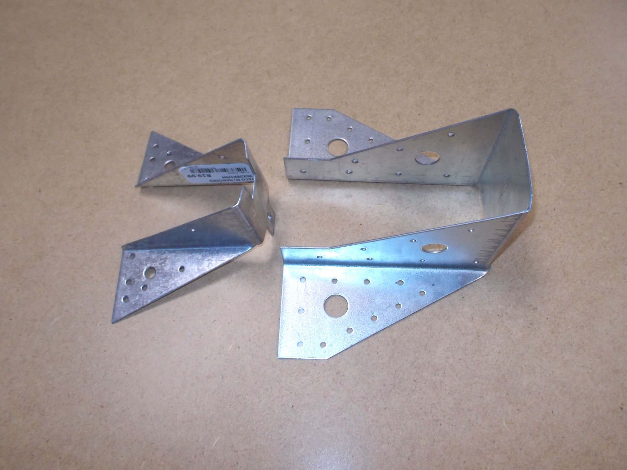
- These smooth-shank cut screws as the name implies, cut their own path through the wood and use a square bit (also known as a Robertson bit) to drive them in.
- This selection of hex head coach bolts are stainless steel, making them ideal for outdoor installations in coastal areas. They are driven in using a nut setter (an attachment for your drill. It incorporates a hexagonal head (there are various sizes available, such as 8mm,10mm and 12mm), and the chisel tip on the bolt cuts its own way into the wood, so no pilot hole need be drilled.
- Another selection of hex-head securing screws.
- Roofing screws should be driven in along the peaks of corrugated roofing, as shown here – and not in the valleys (the same applies, naturally to IBR roofing – the fasteners are driven in through the peaks, but with this caveat… drive them in just far enough to secure the panel, but not so deep than it pulls the flat peak of the IBR section down, to form a valley… this will allow water to pool, and in time the roof might leak at that point). That sounds obvious, but if it can be done incorrectly, someone will manage it! This type of fastener has a sponge washer surmounted by a weatherproof, UV resistant flange with a large cap that clips over the fastener’s head. The cap is attached to the flange with a tiny built-in strap of the same material.
- Another type of roofing fastener. The upper one showing how it all comes together, and the lower one showing the three parts… the fastener, sponge sealer, and cap that is tapped onto the fastener’s head after the fastener has been driven in.
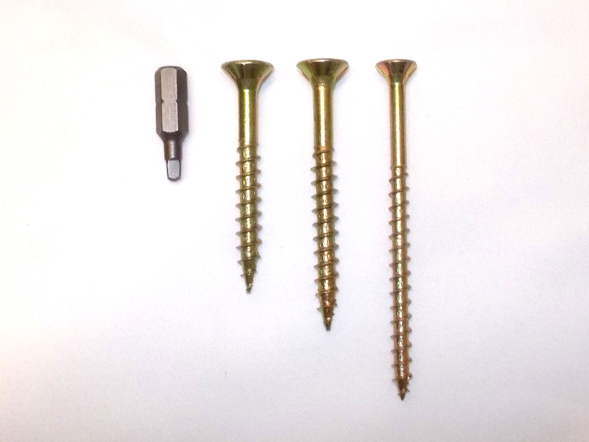
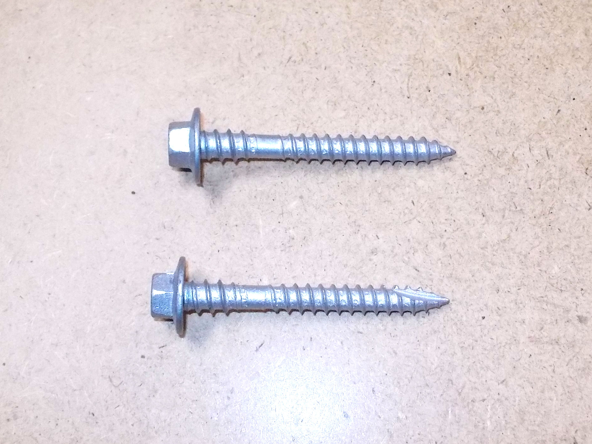
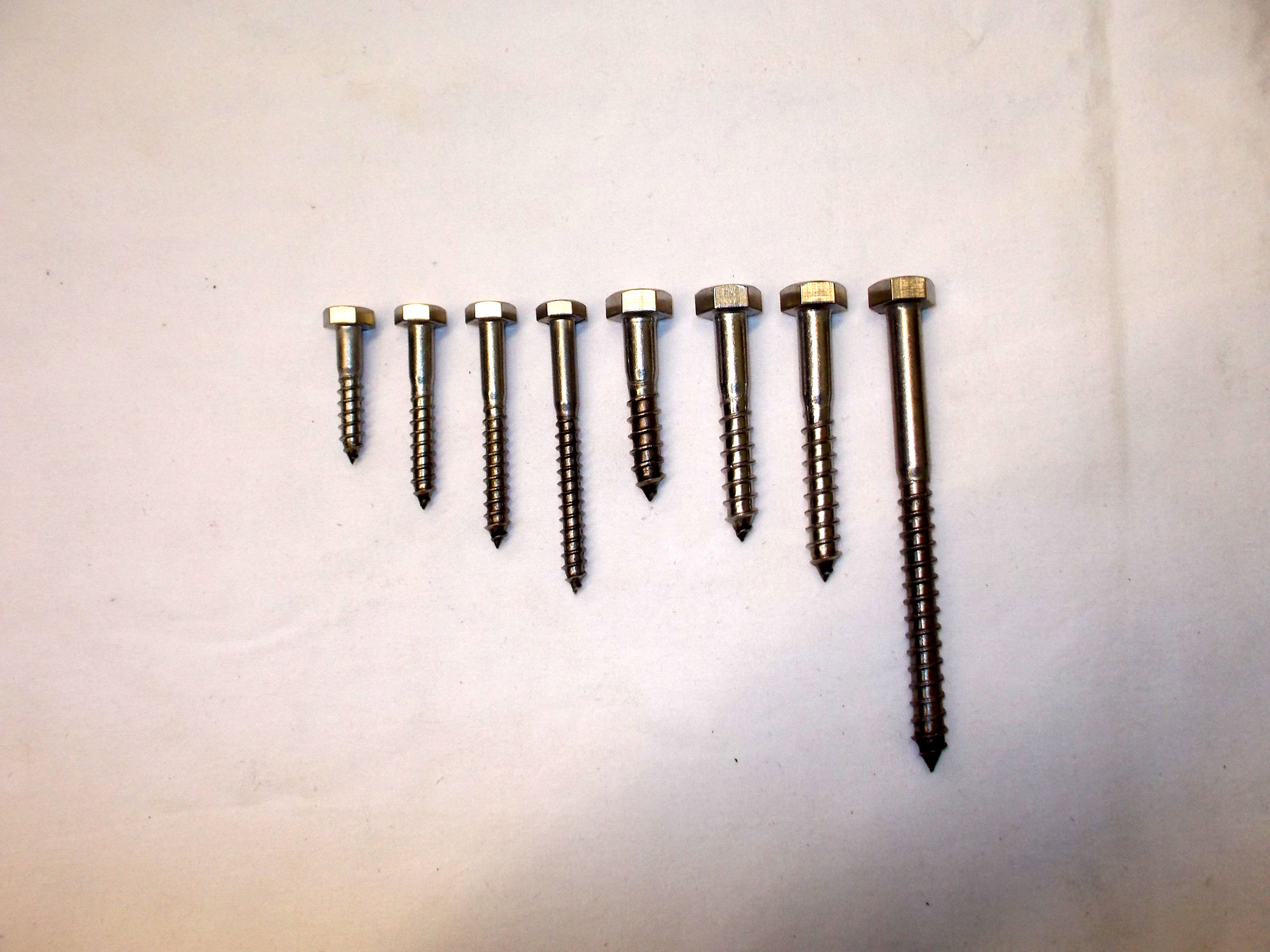
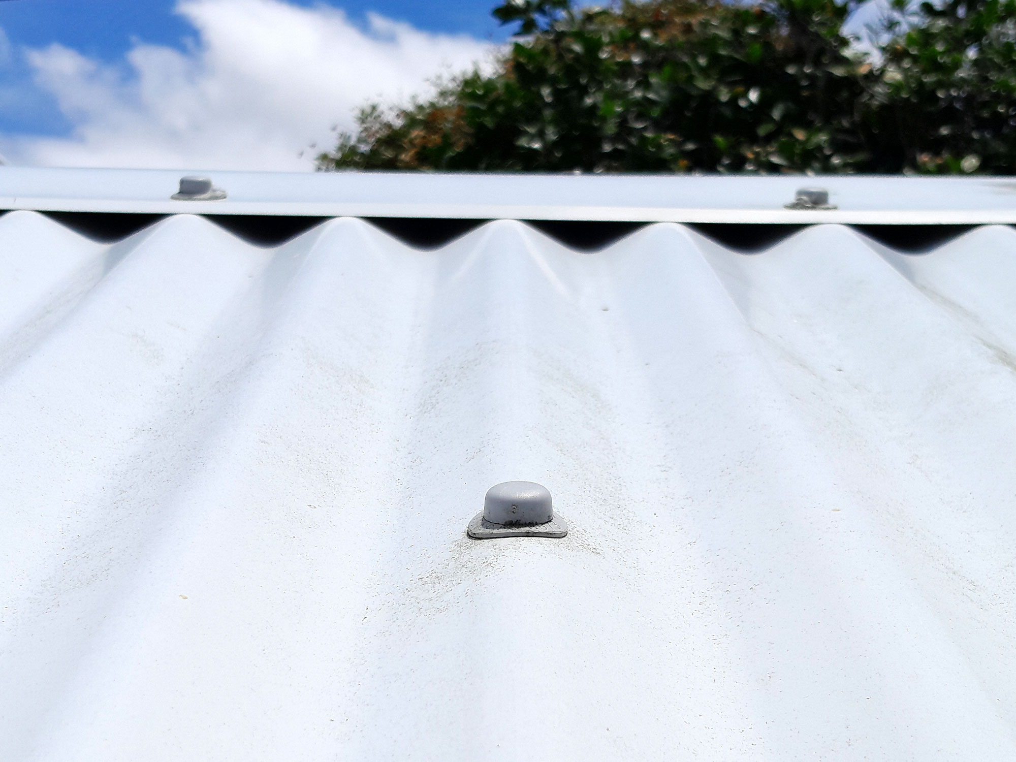
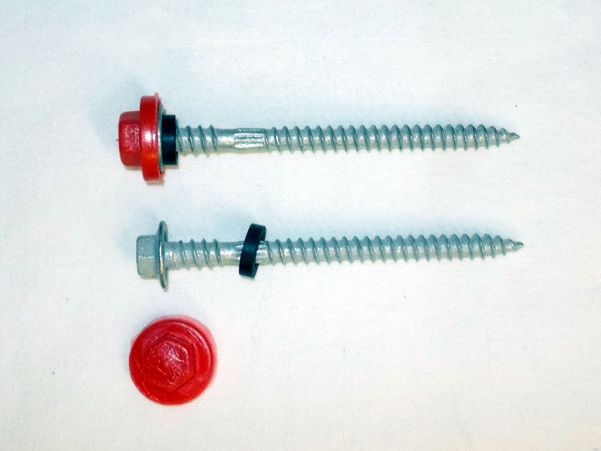
- The difference between meranti (top) and SA pine. The latter is one of your cheapest options, but ideally needs to be well sealed.
- This shows the difference between untreated SA pine (top) and treated SA pine. The different colours are very evident. Ideally, treated pine will have a lifespan of several decades.
- Meranti has a very tight grain, but bear in mind that it is quite variable in its hardness, texture and colour, so ensure that you select pieces of timber that match.
- A series of treated SA pine cross-sections. Your gazebo’s beams would be determined by the size of the structure, and the strength required according to your local weather/wind conditions.
- If you decide upon a square or rectangular gazebo and when you have overlapping ends, as depicted here, you can use half-lap joints – shown by the two lower illustrations – and shape the ends as shown upper right.

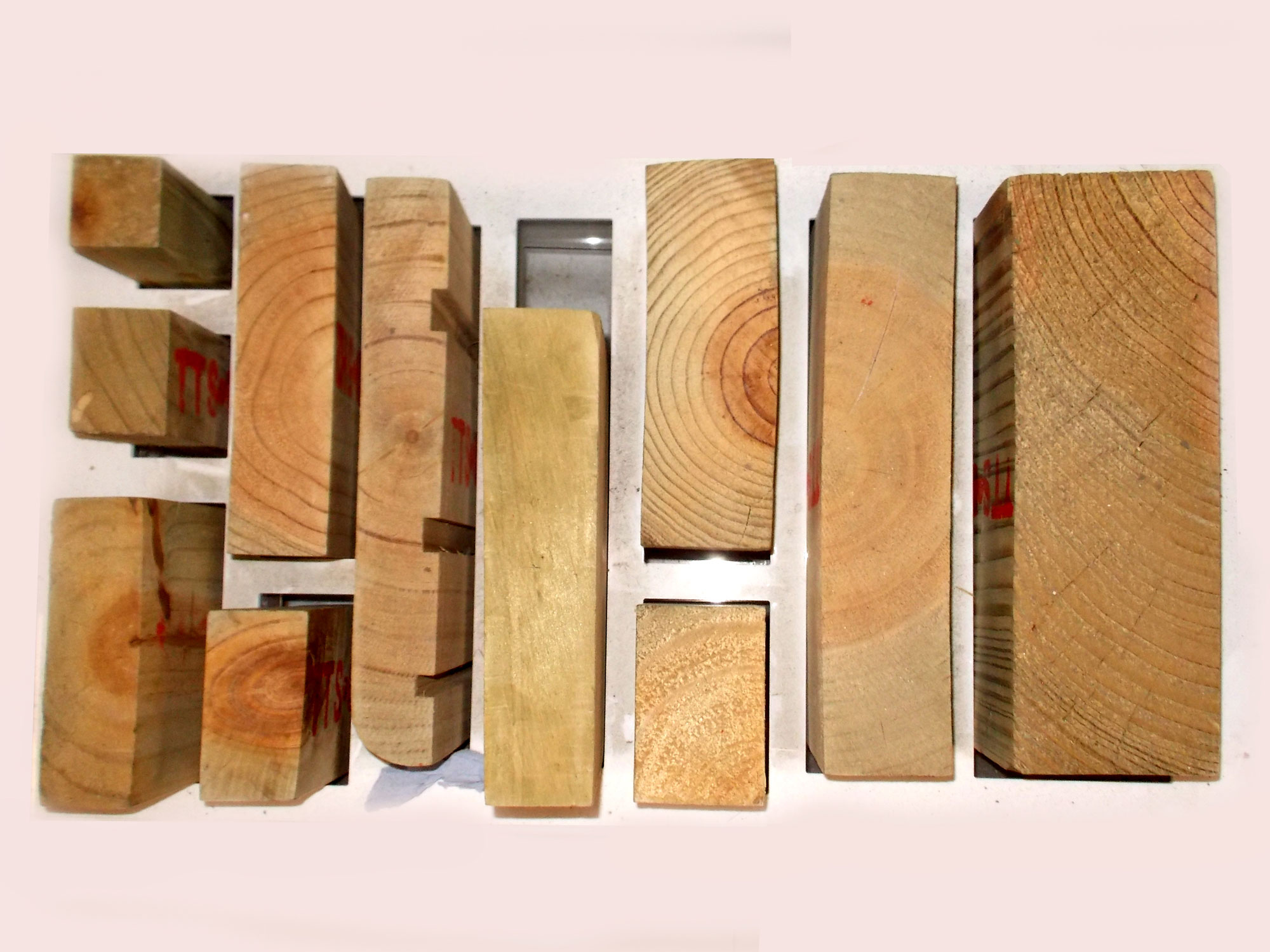
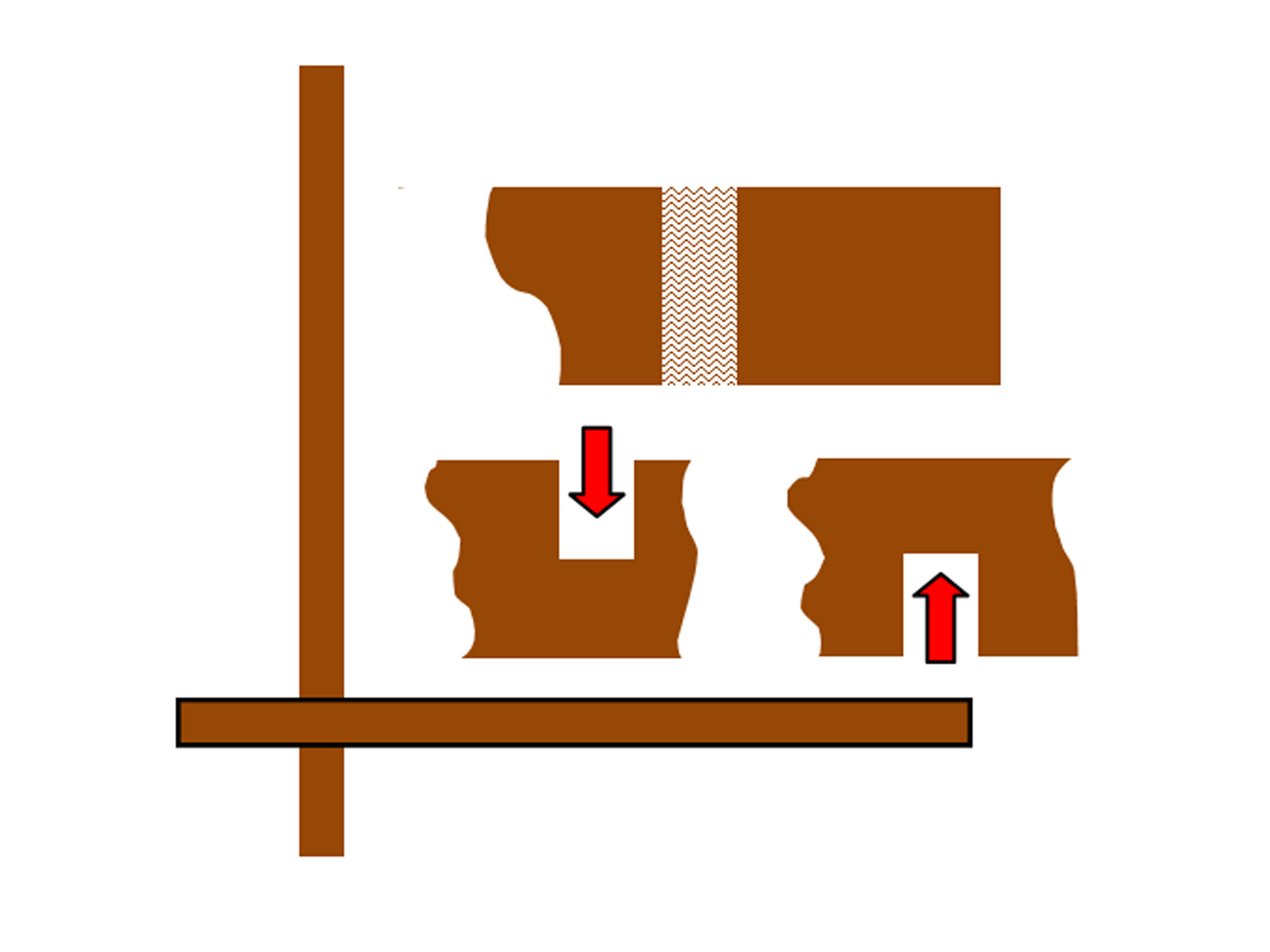
- The parts of a rectangular gazebo roof. As noted in the text, bear in mind that while terms such as beam and rafter are pretty universal, other terms such as stringer may vary. The lower illustration shows the side view of the assembly.
- If you want to pave the floor, you can grout between the slabs with a sand-cement mix. Typically the gap on each side of the slab is about 15mm or so.
- Laying cobbles along the edge of the paved area adds a nice finishing touch.
- For a more natural look, you can simply lay the slabs with a gap of about 15-20mm on each side and allow lawn grass to grow naturally between the slabs. The advantage of this method is two-fold… one, you don’t have the task of grouting between the slabs, and two, if over time any of the slabs sink a little, it is a simple job of lifting out the offending slab/s, adding some filler soil and then putting them back in place – and no regrouting is necessary!
- This galvanised green powder-coated trellis is available in panels such as the six bar 760mm x 1530mm and the nine bar 1140mm x 1530mm. it can be used to act as a climbing frame for a creeper or vine growing up the sides of your gazebo.
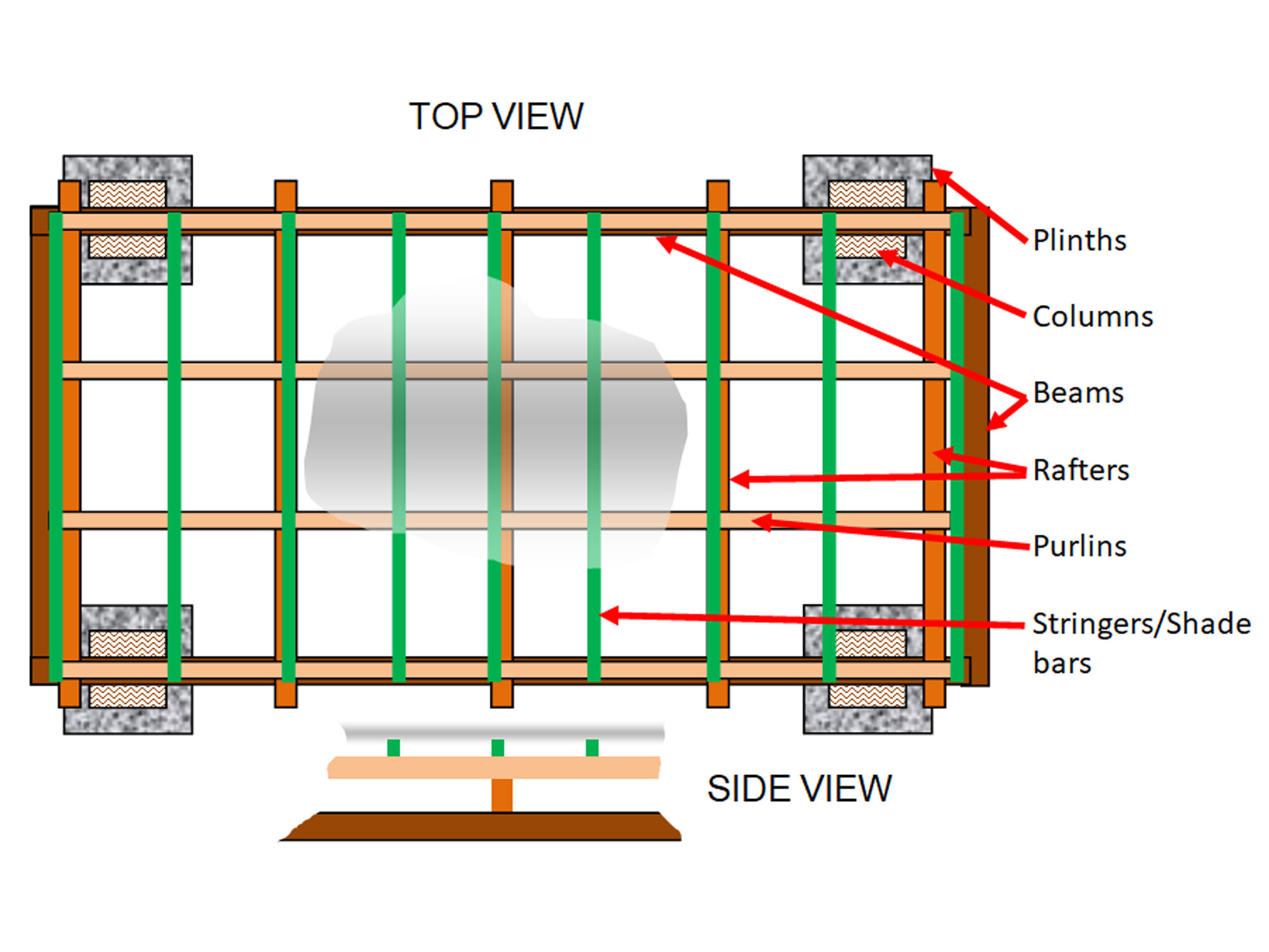
- You can buy expanding trellis, which as the name suggests can be expanded or contracted to fit most spaces. Alternatively a panel such as this one – 450mm x 1500mm – will also work well. It is actually designed for placement on top of a cast concrete slab wall, but will also work well on the side of a gazebo, and as it is treated, will have very good durability.
- Here the ends of a peaked gazebo roof have been adorned with meal artwork. (Source: Wikimedia Commons – Public Domain)
- Here the end beam on a flat gazebo roof has been adorned in the same manner. Note the rafters running between the beams, and the bracing (known as knee braces) visible on the far beam to make the gazebo more rigid. (Source: Wikimedia Commons – Public Domain)
- Here is a selection of just four roof material you might consider using. From top left and running clockwise… tiles, thatch, shingles and thatch with rope overlay. The thatch with or without the rope addition can be used for a very rustic effect. (Source: Wikimedia Commons – Public Domain)
- This shows some of the component parts of a gazebo, this one with a raised floor. The information on the functions of the various component parts listed here, and explained above in the article’s text.
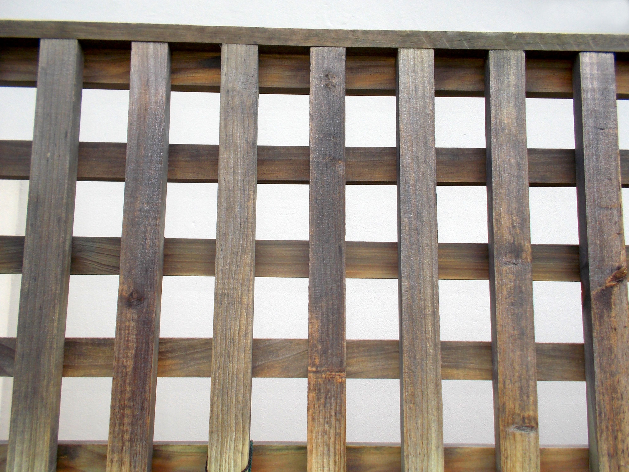
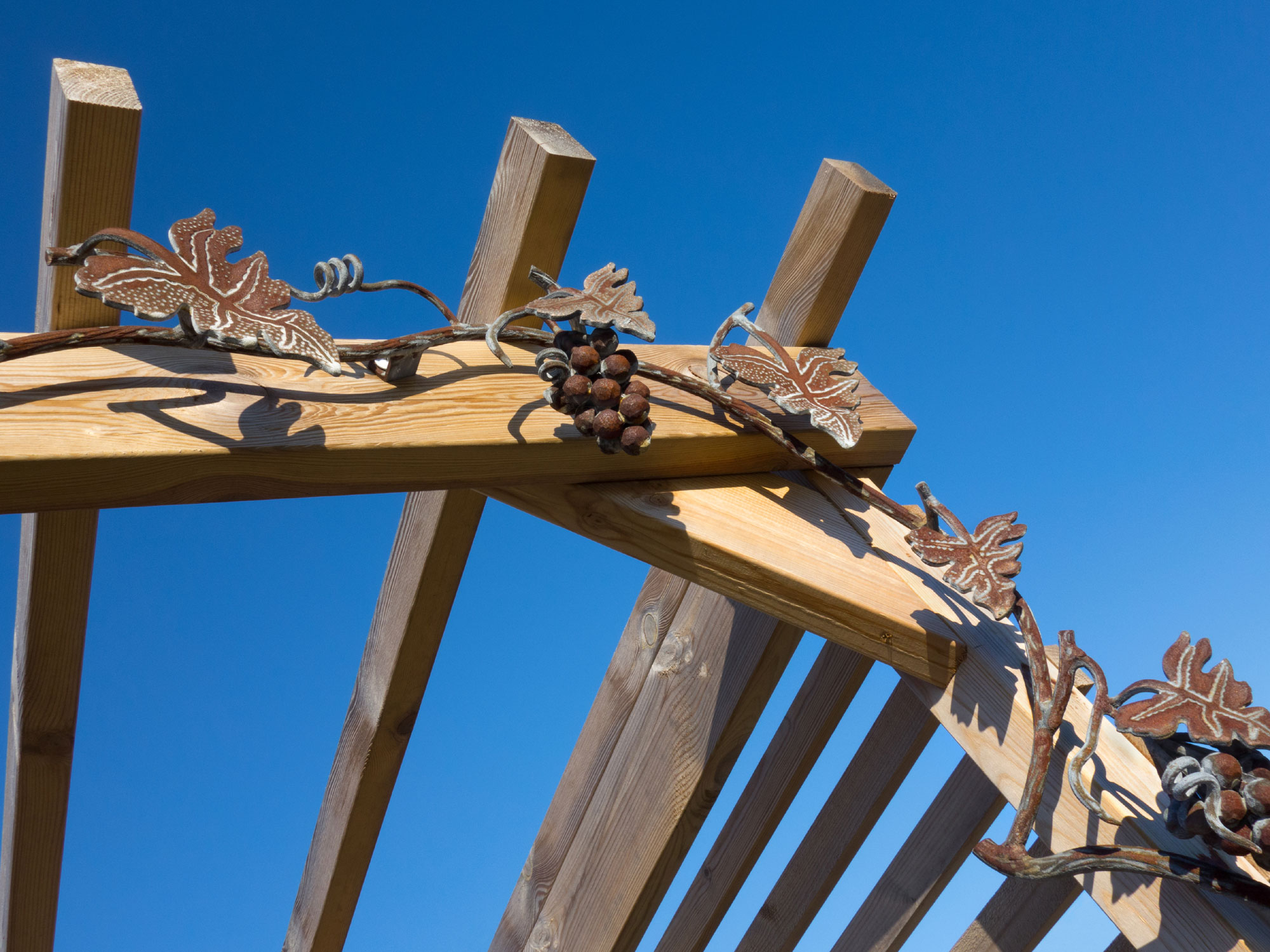
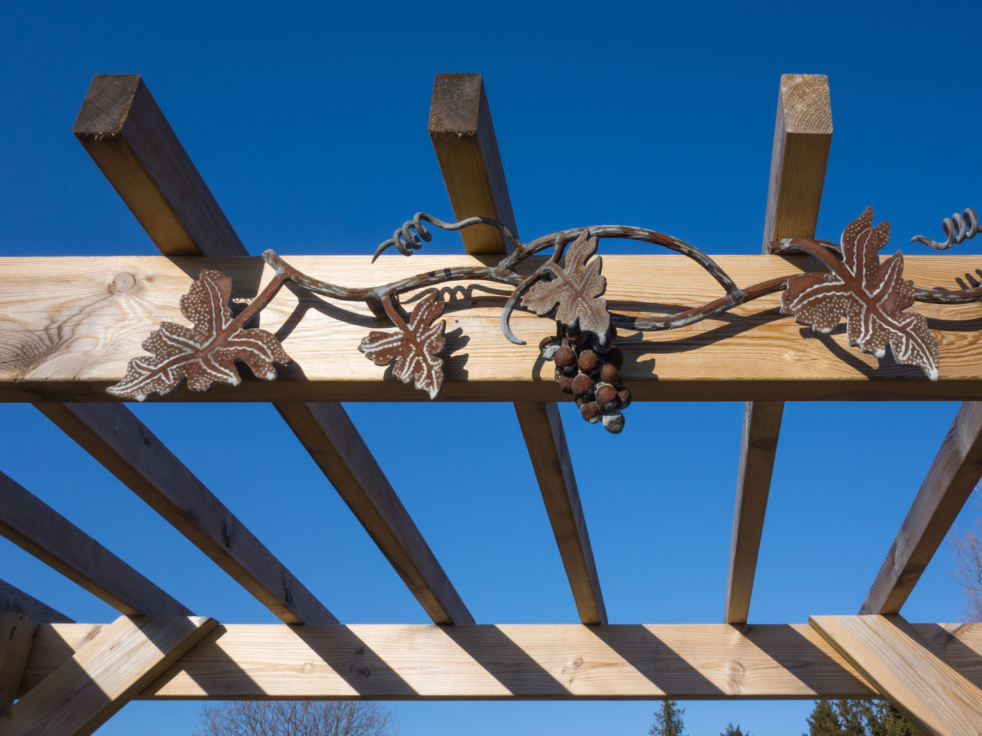

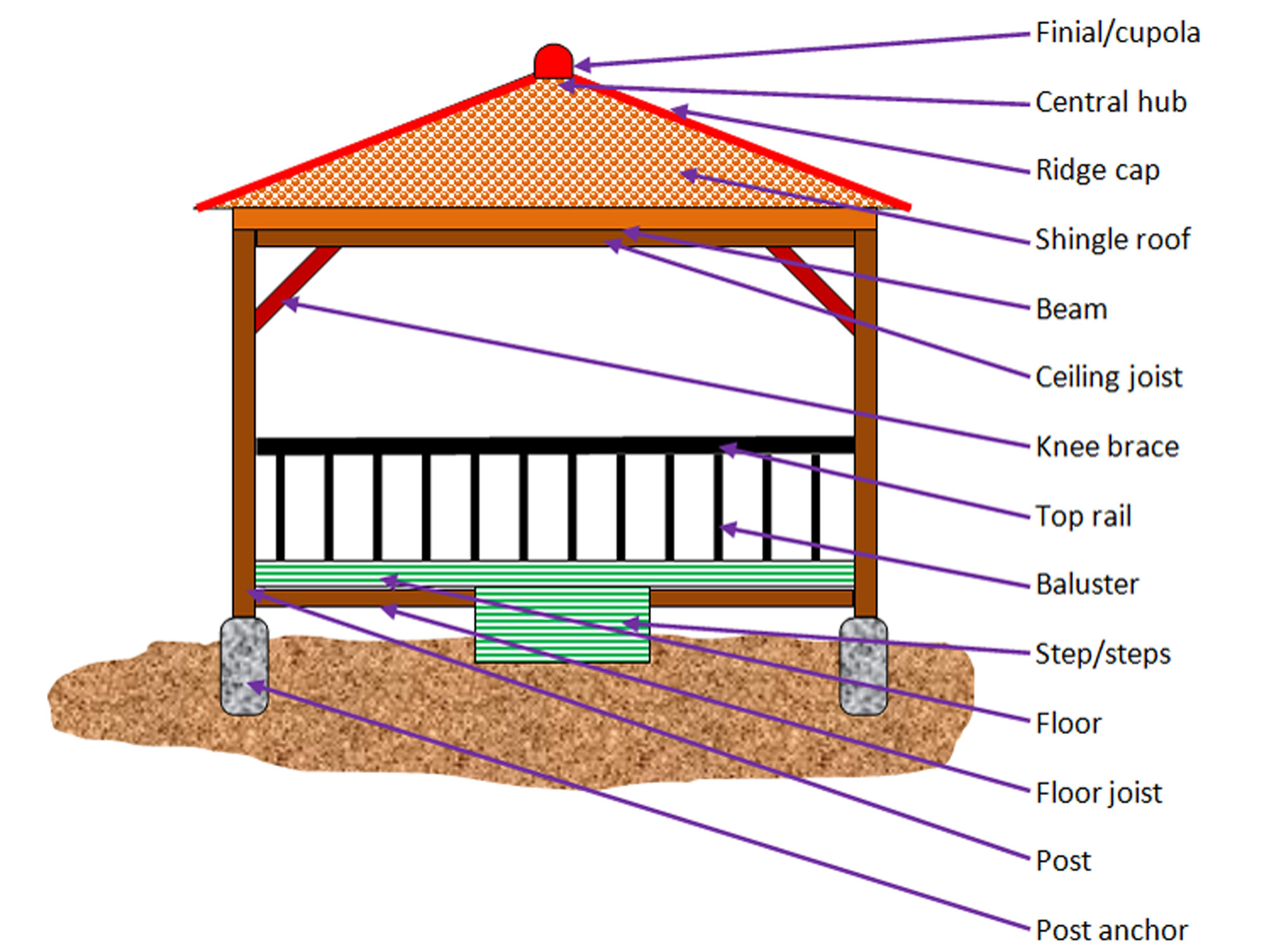
Panel:
Mica Stores stock the timber, trellises, fasteners and brackets etc you will require for your gazebo. Some of the larger branches might also have a garden plants department, or be close to a garden centre. To find your closest Mica and whether or not they stock the items required, please go to www.mica.co.za, find your store and call them. If your local Mica does not stock exactly what you need they will be able to order it for you or suggest an alternative product or a reputable source.

Infused Oil & Pasta Salad
One of the best ways to celebrate Garden Day is by bringing the flavours of your garden straight to the table.
Fresh herbs, homegrown chillies, and garden greens can be transformed into delicious pasta dishes or infused oils that elevate any meal.
It’s a simple, tasty way to enjoy the rewards of your hard work while sharing something special with family and friends.
Rosemary & Garlic Infused Oil
Ingredients:
- 1 cup olive oil
- 2 sprigs fresh rosemary
- 2 cloves garlic, lightly smashed
Method:
- Warm the olive oil gently in a pan (don’t let it boil).
- Add rosemary and garlic, letting them steep for 5–10 minutes.
- Remove from heat, let it cool, then strain into a clean glass jar.
- Use for dipping bread, drizzling over roasted veggies, or tossing into pasta.
Chilli & Basil Infused Oil
Ingredients:
- 1 cup olive oil
- 2 fresh red chillies, sliced
- 1 handful fresh basil leaves
Method:
- Heat oil gently, add chillies and basil.
- Let simmer on low for 5 minutes.
- Cool, strain, and store in a glass bottle.
- Perfect for salads, grilled meats, or as a pizza drizzle.
Fresh Herb & Veggie Pasta Salad
Ingredients:
- 300g pasta (fusilli or penne works best)
- 1 cup cherry tomatoes, halved
- 1 cucumber, diced
- 1 red onion, finely chopped
- 1 cup feta cheese, cubed
- ½ cup olives (optional)
- Fresh herbs: parsley, basil, or mint
Dressing:
- ¼ cup olive oil (or infused oil for extra flavour)
- 2 tbsp lemon juice
- 1 tsp honey or sugar
- Salt & pepper to taste
Method:
- Cook pasta until al dente, drain, and let cool.
- Combine pasta with veggies, feta, and herbs in a large bowl.
- Whisk dressing ingredients together and pour over salad.
- Toss gently and chill for at least 30 minutes before serving.

Bloom Board
What is a Bloom Board?
A Bloom Board is like a vision board for your garden. Instead of focusing on life goals or dreams, it’s all about capturing the look, feel, and mood you’d love your green space to have.
Whether you’re dreaming of a wildflower corner, a calming herb patch, or a colourful balcony full of pots, a Bloom Board helps bring your garden ideas together in one inspiring place.
It’s a fun, creative activity that anyone can do – no green thumb required! A Bloom Board can spark fresh ideas, guide your planting choices, and keep you motivated as you grow your little piece of paradise.
How to Make Your Own Bloom Board
Gather Inspiration:
Look through gardening magazines, catalogues, Pinterest, or even photos from your own garden. Choose images of plants, flowers, colours, and garden styles you love.
Choose a Base:
Use a piece of cardboard, a corkboard, or even a digital platform like Canva or Pinterest to build your board.
Add Colours & Textures:
Collect paint swatches, fabric scraps, or pressed flowers to show the colours and textures you’d like in your space.
Include Your “Garden Goals”:
Write down a few words or phrases that describe the vibe you want: calm & cozy, bright & cheerful, or wild & free.
Arrange & Stick:
Play around with your images and ideas until it feels right, then glue, pin, or save them in place.
Display Your Board:
Put your Bloom Board somewhere you’ll see it often – in your kitchen, by your desk, or near your garden tools. It will remind you of the beauty you’re working towards.
The best part? A Bloom Board is totally personal. It can be big or small, detailed or simple – the only rule is that it should make you smile and inspire you to grow.

DIY Garden Hacks
Looking to celebrate Garden Day without spending a fortune? We’ve rounded up some simple, budget-friendly hacks that make it easy to add charm, creativity, and a touch of magic to your outdoor space. Each idea is quick to do, cost-effective, and perfect for bringing your garden to life.
Eggshell Fertilizer:
Crush used eggshells and sprinkle them around plants – they add calcium to the soil and help deter slugs and snails.
Banana Peel Plant Food:
Chop banana peels into small pieces and bury them in the soil near your plants – they release potassium and phosphorus as they break down.
Coffee Grounds Boost:
Used coffee grounds can enrich soil with nitrogen. Just mix them into your compost or directly into the soil for a natural boost.
Water Bottle Drip System:
Poke small holes in a plastic bottle, fill it with water, and bury it near your plants. It slowly releases water, keeping soil moist for longer.
Cinnamon for Seedlings:
Sprinkle cinnamon on soil when starting seeds – it helps prevent fungal diseases like damping-off.
Plastic Spoon Plant Labels:
Recycle old plastic spoons, paint the handles, and write plant names on them – simple and free garden markers.
Epsom Salt for Greener Plants:
Dissolve a tablespoon of Epsom salt in a litre of water and spray on leaves – it adds magnesium, which helps plants grow lush and green.
Vinegar Weed Killer:
Spray white vinegar directly on weeds growing in cracks or pathways (but avoid your flowers and veggies).

How to Celebrate Garden Day
Celebrating Garden Day in-store with your staff is about more than just a fun activity. It’s a way to build connection, boost morale, and create a positive workplace culture.
Taking time to celebrate together shows appreciation, encourages creativity, and gives your team a chance to relax and enjoy something different.
Plus, shared celebrations foster teamwork and can make your store feel like a community, not just a workplace.
Staff Crown-Making Contest – Let Customers Vote for the Best One:
Get your team involved by hosting a fun flower crown-making contest before or on Garden Day. Each staff member creates their own crown, then customers can vote for their favourite in-store. It is a light-hearted way to spark interaction and bring festive energy into your store.
Pot Painting Station:
Set up a creative corner with terracotta pots, paints, and brushes where customers can decorate their own pot. Once painted, they can plant a small seed or seedling to take home. This hands-on activity is great for kids and adults alike, leaving them with a lasting Garden Day keepsake.
Garden Day Photo Booth:
Create a simple photo booth in-store with a floral or garden-inspired backdrop, props like watering cans and sun hats, and a Garden Day sign. Encourage customers to snap photos, share them online, and tag your store. It is an easy way to spread the celebration beyond the store walls.
Spread the Word:
Use your social media platforms, in-store posters, and community networks to promote Garden Day. Share posts from Mica’s main page, highlight your store’s activities, and invite customers to post their own celebrations with #GardenDaySA #MicaHardware. The more voices join in, the bigger the buzz!
Decorate the Store:
Transform your store into a celebration of nature with flowers, greenery, and garden-themed displays. Add splashes of colour at your entrance, sprinkle petals across a display table, or create a flower wall where customers can pick a bloom to take home. The festive décor sets the mood and makes Garden Day feel special.


What Is Garden Day?
Garden Day is all about pausing to reconnect with the natural world and finding joy in the green spaces around us.
It’s a chance for both seasoned gardeners and complete beginners to celebrate plants, flowers, and the outdoors in their own way. Some may spend the day planting something new, others might tend to what is already growing, or even share a gardening tip or two with neighbours.
At its heart, Garden Day highlights the calming, restorative power of nature and the sense of togetherness it inspires. Whether your sanctuary is a full garden, a few pots on a balcony, or even a windowsill plant, this day is an invitation to slow down, breathe deeply, and take pleasure in nurturing life.

Protecting your wood window frames against wet rot
In this instance, the window frame is on a south-facing wall that seldom gets direct sunlight, and to boot has also been exposed to irrigation water for some time, and the beading had rotted. So the remedy was to replace the rotted beading, while also ensuring that the good frame was properly protected.
Materials:
- Wood treatment product that protects against wet rot and seals wood effectively
- Replacement beading
- Small pack of 30mm panel pins
Method:
- First of all, if possible remove or stop the source of the water (in this case, irrigation) and remove the rotted beading.
- Then brush out the space it occupied, and also remove any protruding panel pins, or where they have rusted away, tap them down flush or below the surface of the frame. It is important to ensure that every speck of loose debris is removed.
- At this stage I cut the replacement beading and did a dry fit.
- Ensure the replacement fits properly, and then remove it and apply at least 2-3 coats of sealer, taking care to ensure the ends are fully sealed. This will take a couple of days as you must leave the various coats to dry properly.
- While that is going on, apply masking tape to the edge of the frame to keep any product from dripping on to the window sill.
- Then apply a number of coats of the product to the frame, allowing each adequate time to dry properly. You can use a brush, or…
- As I did here, I used a tablet sponge secured on a length of wire, to apply the finish. It just cuts down on cleaning afterwards. And in any event you are not aiming for a Chippendale finish, right?
- Meanwhile, I drove a number of evenly spaced panel pins into the prepared replacement beading, just far enough that only their tips were penetrating the lower edge. It is much easier to do it this way than driving in the panel pins while holding the beading in place. That way tends to make you swear!
- I laid masking tape along the window pane, as shown, about 8mm up from the bottom edge, plus a second strip along the window frame, on the line at which the beading meets the frame. You will see why, very shortly.
- Then I applied a generous bead of clear silicon sealer along the surface, and pane, and also to the lower surface of the replacement beading.
- Then I pressed it into place, and…
- Using a piece of scrap 3mm plywood as a glass protector so I would not crack the window pane, I tapped the panel pins home, securing the replacement beading securely in place. And as the panel pins had already been seated, all I had to was press the beading down firmly in place and the hold the plywood protection panel against the pane as I tapped in the panel pins. Easy!
- Finally, I removed the masking tape, in so doing removed any excess silicon that had oozed out, thus making for a very neat result.
- And here it is – well, part of it, anyway.
- Here’s a view of the complete repair.
- And here is the final, completed job… the new beading and frame are completely sealed off from ANY moisture, and a couple of coats of the final finish, a mahogany gloss varnish, not only completes the job, but also protects the new panel pins from corrosion as well.

Panel:
These materials are available at Selected Mica Stores. To find your closest Mica and whether or not they stock the items required, please go to www.mica.co.za, find your store and call them. If your local Mica does not stock exactly what you need they will be able to order it for you or suggest an alternative product or a reputable source.
Project guide
- TIME: little more than an hour, but spread over a couple of days for repeat applications of the product
- COST: +-R150, depending on the treatment you use and the cost of any replacement beading
- Skill: 2
- Assistant: No
Tools required:
Panel saw to cut the beading, mitre box, and hammer