22 June 2023
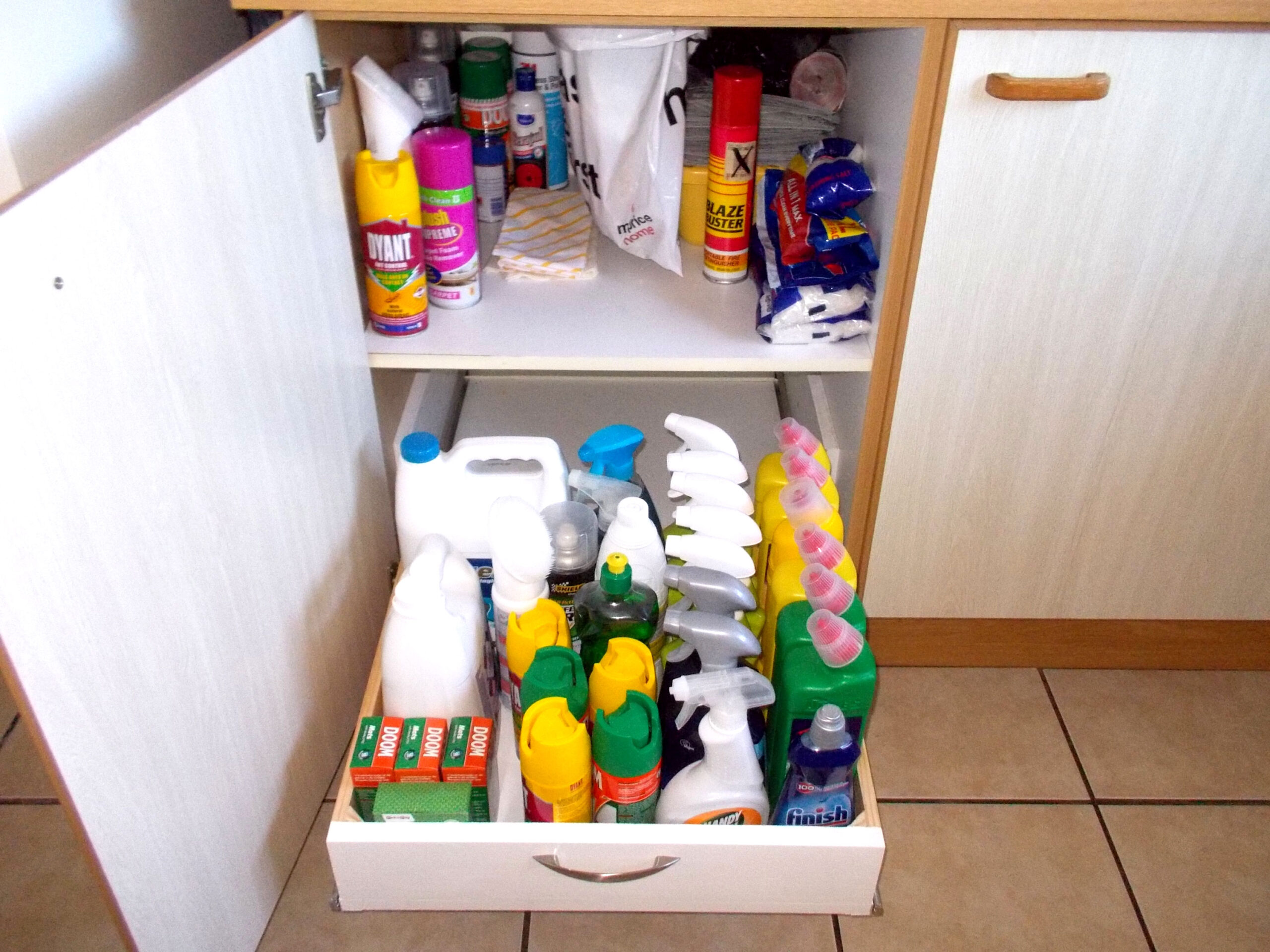
Variation on a theme… the kitchen cabinet drawer
This project requires very precise measuring and cutting, but get that right and what you will end up with is a great deal more convenience as you will be able to easily get at any pot, pan, dish or in this case household cleaner, detergent, pest aerosol or whatever else you store it wherever it is in the cabinet… even in the deepest recesses at the very back. Essentially the ‘back’ disappears, because rather than reaching in and having to grovel around at floor level, you will be pulling the drawer out – and then be able to grab whatever you need from directly above. So much easier!
Note also that this project is ideal for a linen cabinet or in fact for just about any other deep cupboard or cabinet, whatever its purpose. In this case… it is used to store household detergents, sanitisers and so on.
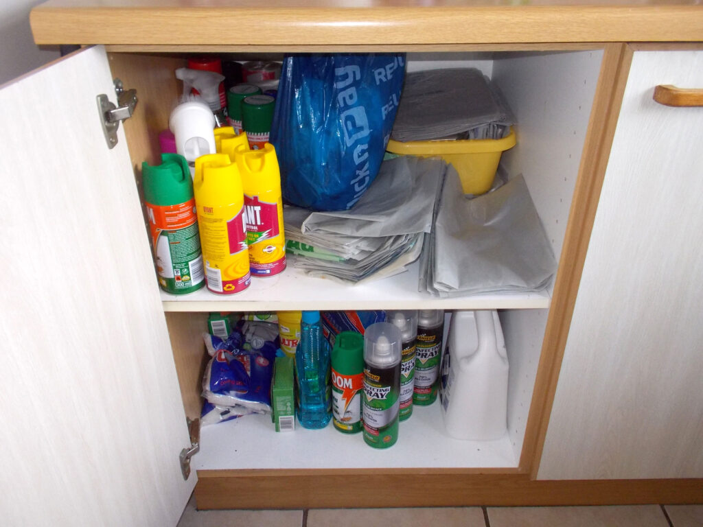
Here I installed just the one drawer as there is a kitchen refuse disposal unit set into the countertop and the refuse bag (the blue one in the first image) is suspended from the unit and pulling assorted items out from under it if they are stored in a drawer would in all likelihood tear the bag. In any event, as mentioned, items on the shelf are easy to reach.
I have not gone into great depth regarding the sizes of the drawer, because your cabinet’s dimensions may differ. There are two measurements that are crucial, however:
- The sliders used in this project, plus the aluminium supports and 16mm chipboard slider mounts each have a total width of 30mm. Hence in this case it means the drawer is 507mm wide, even though the cabinet itself has an internal width of 568mm. That difference of 61mm comprises the above-mentioned sliders, mounts and aluminium reinforcing support. Clear as mud?
- The cabinet is 555mm deep, which means the drawer needs to be no more than 500mm as there has to be clearance at the front for the handle so that the cabinet door can close properly.
- Note that wood 96mm high was been used for front, rear and sides of the drawer. This is because it will be holding bottles of detergent, bleach and so on, and one doesn’t want any bottles tipping over as the drawer is pulled out or pushed back into the cabinet.
In this case I used 16mm chipboard 455mm wide. I could have gone with the 530mm, but that would have meant trimming it down to 500mm or so – with some wastage. In any event, items with handles could be stored with their handles overhanging the back of the drawer.
Materials:
- BisonBord® 16x455mm wide – one length 850mm long cut to a base of 455mm deep by 506mm wide and two slider mounts each 450mm long by 170mm wide
- SA pine:
- 22x96mm – one length of 1200mm cut to front and back sections, each 506mm long
- 12x96mm – one lengths of 1m cut to two sides each of 412mm
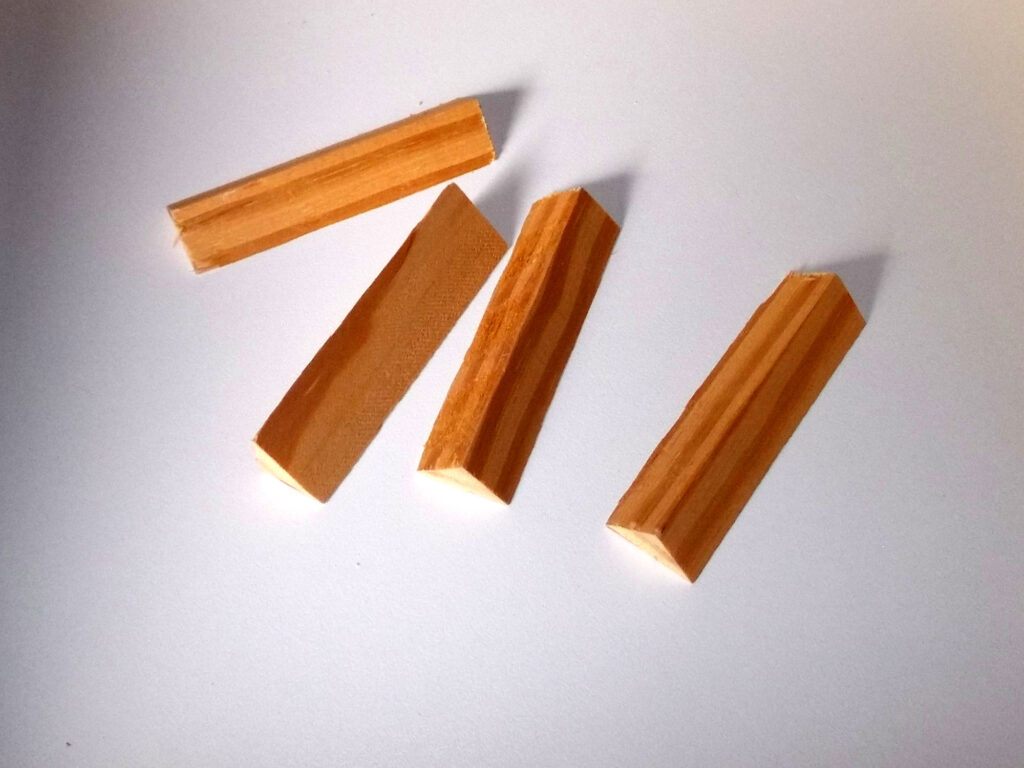
- 500mm length of 22mm 45° quadrant cut to four lengths of 96mm as corner reinforcements
- Aluminium 19x19x1.5mm extrusion – one length of approximately 1m cut to two lengths of 455mm to act as reinforcements to the slider/drawer fixing
- Handles – one brushed satin
- Ball bearing slides (zinc finish) – one 500mm set. Maximum weight bearing should not exceed 25kg. However, you can use heavier duty sliders with a rating of 45kg if you wish. They are the same thickness as the ones used here, but are deeper
- 6x16mm pan-head screws to attach the slider bodies to the sides
- 6x30mm pan head screws to attach the slider sections to the sides of the drawer
- Front and back attachment screws – 6x41mm drywall screws
- Edging tape – self-adhesive or iron-on – one length of 1m, cut to fit and attached to tops and front, if necessary, of the two slider BisonBord® mounts
- Wood glue
- Finish of your choice – I used high-gloss white enamel for the front panel.
Method:
- The cabinet before the drawer was installed… items right at the back of the top shelf were and relatively easy to reach, but those at the bottom of the cabinet far less so. Also note again, the blue refuse bag, which precluded a second drawer to replace the shelf.
- First I cut the two slider chipboard mounts, as per the cutting list in the materials, above). I selected the already edged front end as the front end for the mounts once installed.
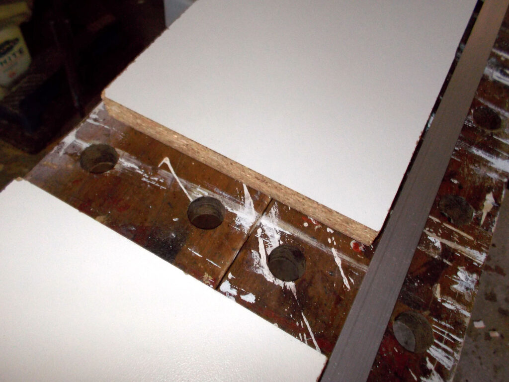
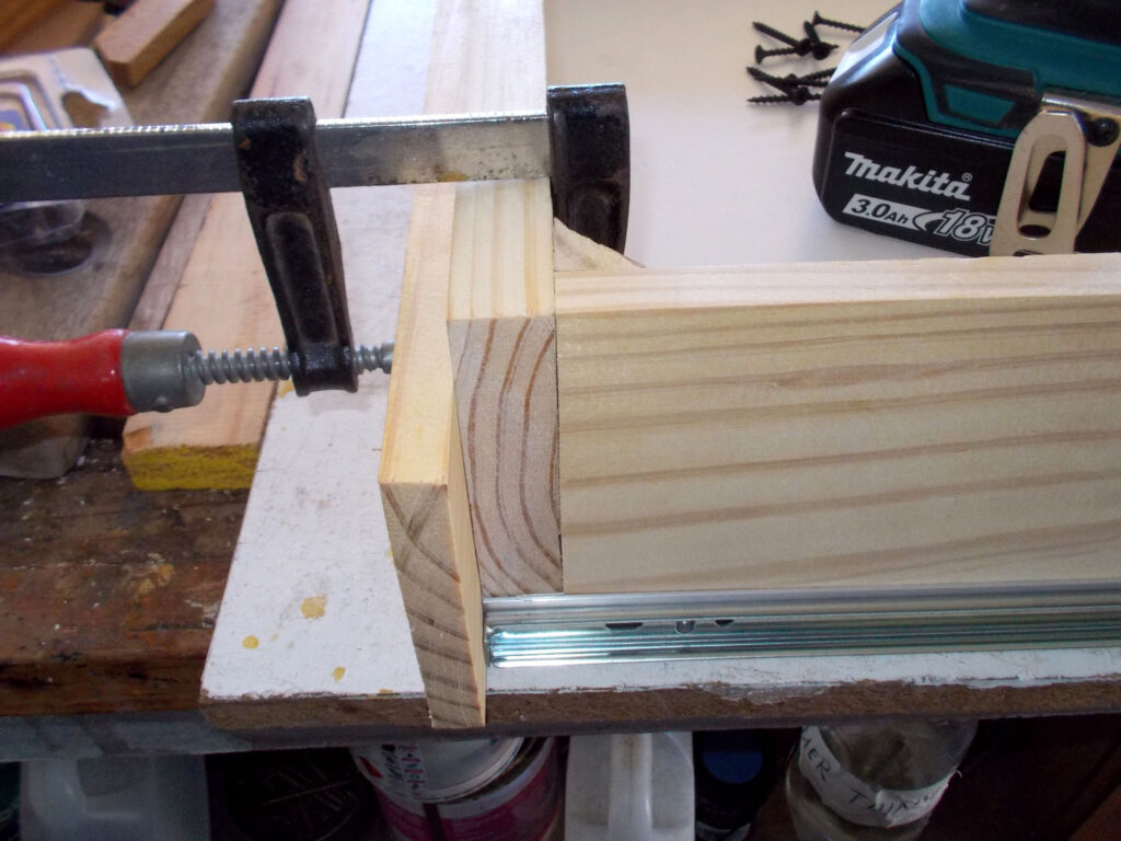
- I clamped both mounts end to end.
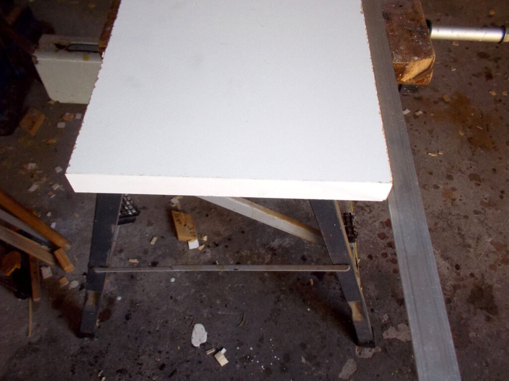
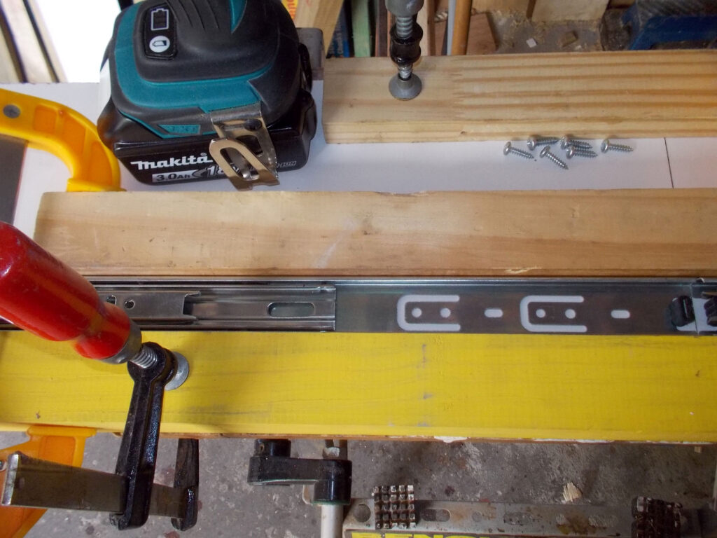
- Then I clamped a length of 44x44mm offcut – the yellow painted wood – hard up against the bottom edge of the mounts.
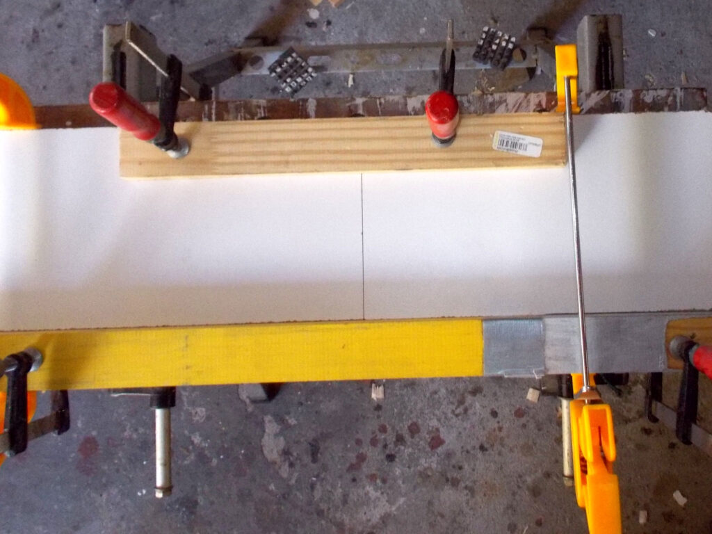
- Then I positioned the sliders hard up against the above-mentioned offcut and meeting each other where the mounts were touching – i.e. what would be the rear edge of the mounts and the sliders. This would ensure that the sliders would be exactly flush with the bottom edge of the mounts and with the back of their respective mounting panels.
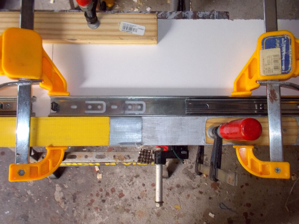
- I secured the slider bodies using 6x16mm pan-head screws.
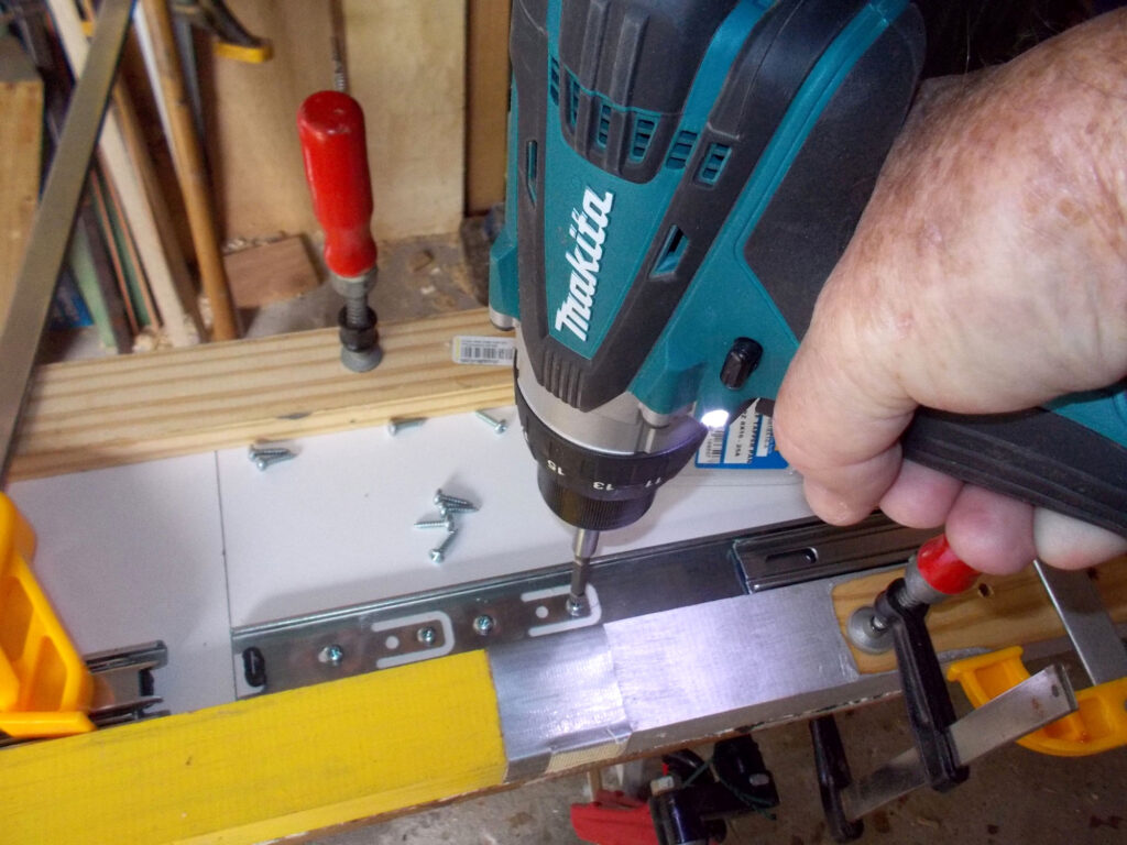
- This shows the rear end of one of the slider bodies, securely attached to its mount with four screws. This will ensure that the rear of the slider will be very secure when the drawer is fully open; remember there is a turning force on the rear of each slider (the drawer will be trying to tip downwards when fully extended).
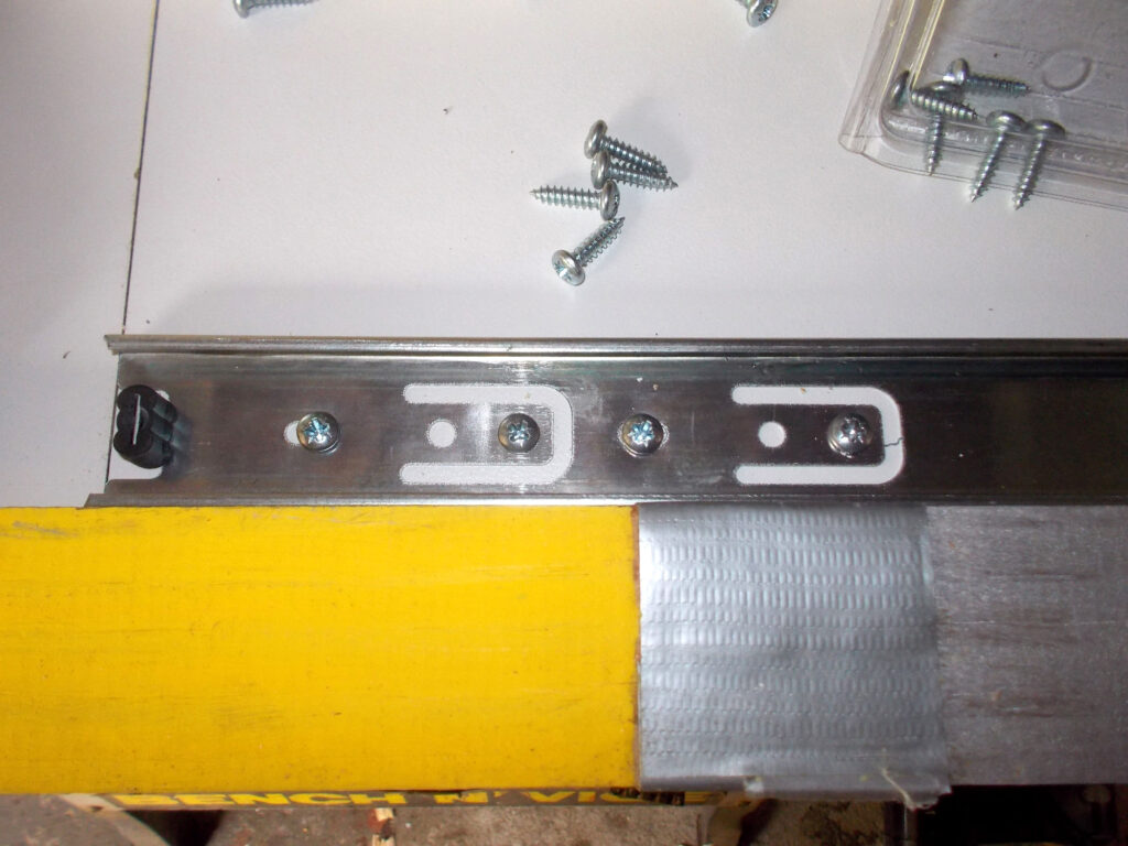
- This shows the front of the slider main body, also attached using the same screws, but not as many required.
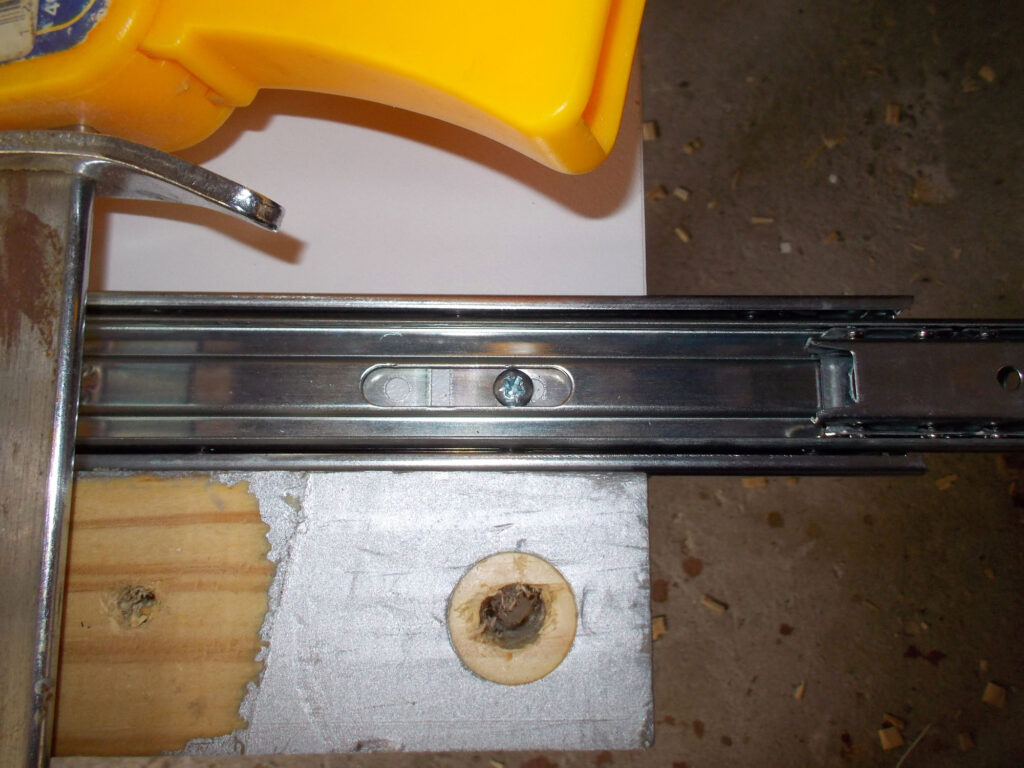
- As you secure each screw in position, operate the slider to ensure that there is no binding. The action should be smooth. (Refer to the panel which shows you how to separate the slider runner [attached to the drawer] from the slider body [attached to the mounting panel].)
- With the slider bodies fully secured to their mounting panels, I applied the edging tape along the top edge of each, using The Boss’s iron to do the job. We are still married after 48-49 years … just!
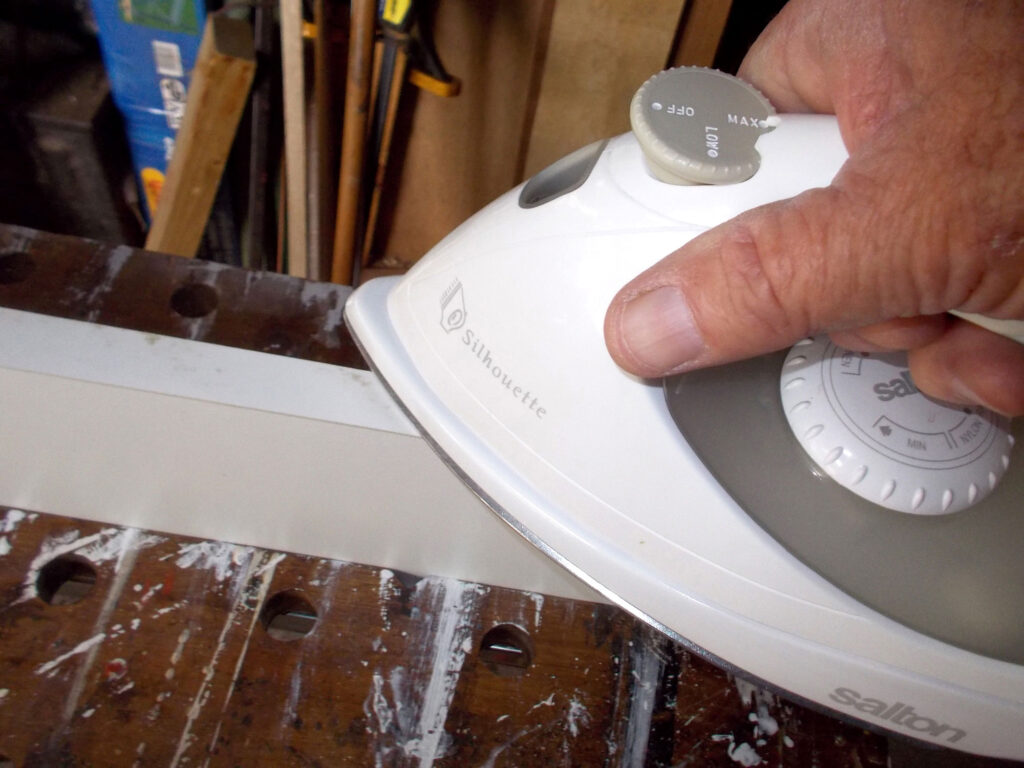
- The edging is slightly wider than the 16mm of the chipboard mounts so it will be very carefully trimmed back using a utility knife.
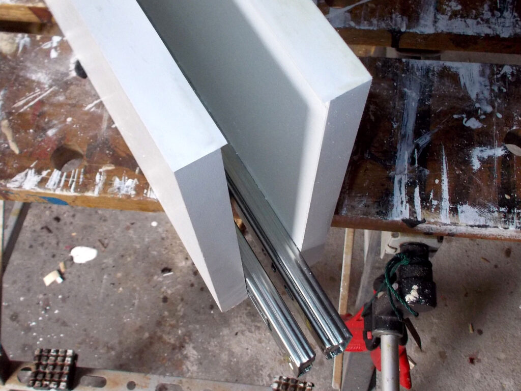
- Now for the aluminium reinforcing support… first I cut the drawer base 455mm deep by 506mm and with the aluminium’s rear edge flush with the rear of the base, marked off the cut line at the front.
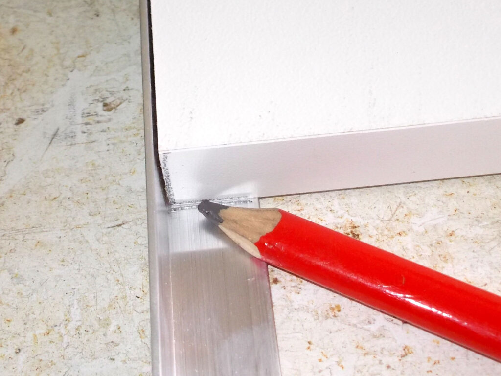
- You can cut it with a hacksaw and then use a metal file to neaten the cut ends.
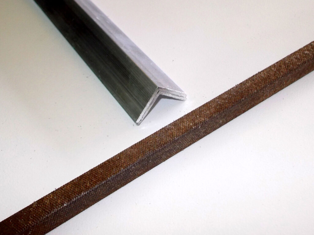
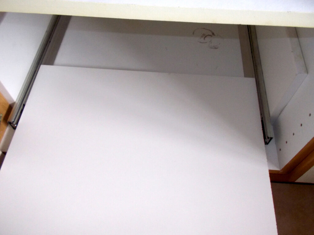
- At this stage, with the aluminium extrusions held in position against the sides of the base, I did a dry-fit with the slider mounts in position on each side of the cabinet.

- Run the base in fully as it will be in its final closed position so that you can check full and free movement along the entire depth of the drawer and cabinet. If it binds at all, then VERY JUDICIOUSLY sand or cut along one edge to reduce the width by a half a millimetre or so. If you do not do this check now and complete the drawer, you will find it will not fit and you will swear as making any adjustments at that stage will be difficult if not impossible.
- Having confirmed that it fits, you can measure off the drawer’s 22x96mm front and rear pieces. The easiest way is to position the base flush with one end of the front piece as shown here.
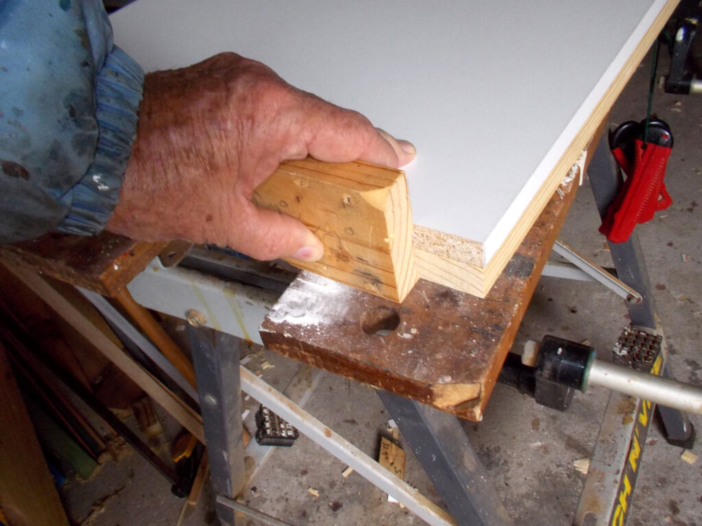
- Now mark off the cut line on the other side of the base. Then repeat this procedure with the rear piece.
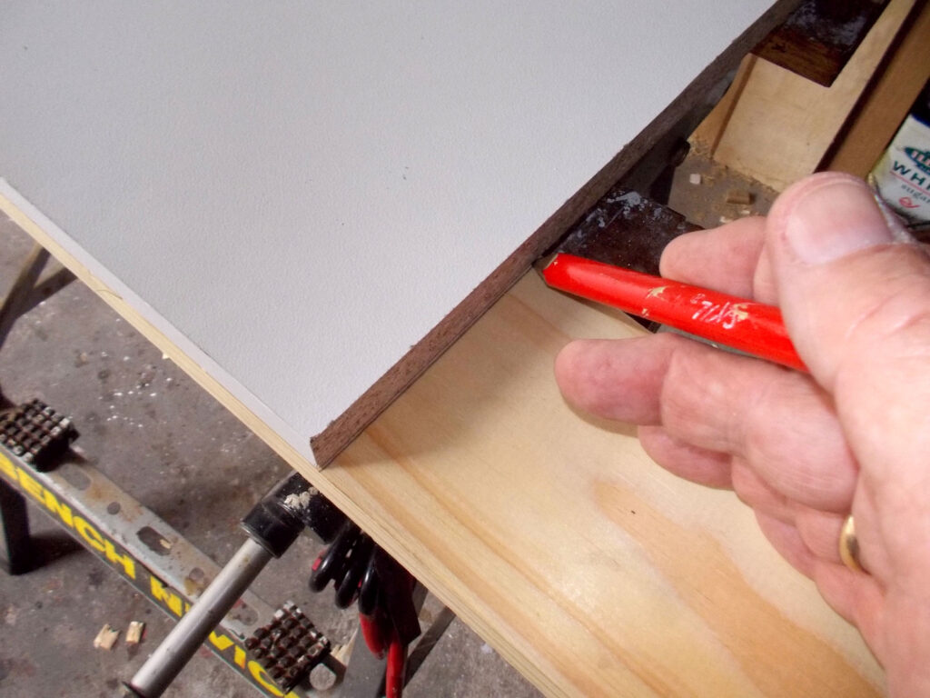
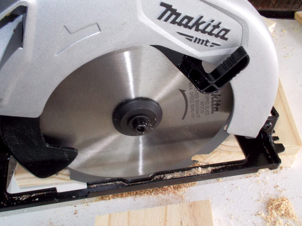
- Now, using a circular cut-off saw cut the front and rear pieces to length. Using this type of saw will give you great results if you ensure you have lined everything up properly.
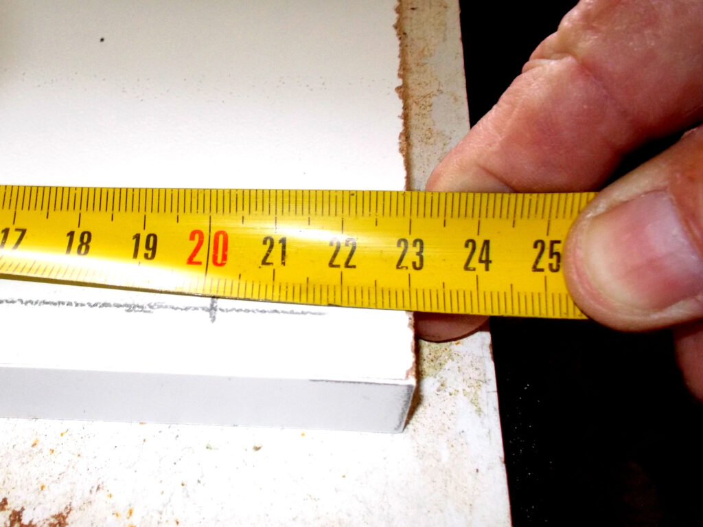
- As the front, rear and sides of the drawer rest on the base, I used quite a few screws to ensure a very secure fixing between all five components. So, with the first 6x41mm drywall screw to be positions 23mm in from the edge, I marked off the positions of the rest, along a line 12mm in from the edge of the chipboard base.
- As you can see I did not spare myself. Exact positioning of the screws is not vitally important as they will not be visible, but just ensure there are sufficient to really secure the front and read to the base (you won’t be able to use wood glue as the board has a coating that is impervious to glue). However, I did slightly bias the attachment towards the middle of the base to counter any tendency whatsoever of separation.
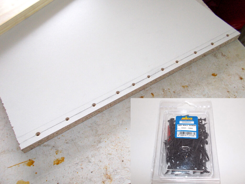
- With the front clamped in position on the front, I drove in the screws, countersinking them slightly so that their heads were flush with what would be the base lower surface.
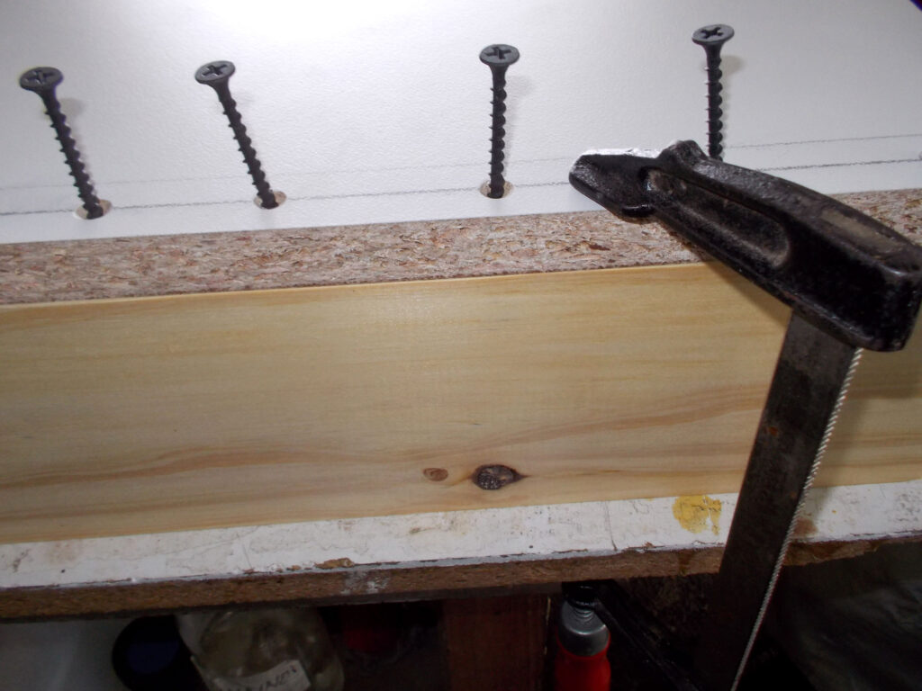
- I repeated the procedure with rear piece.
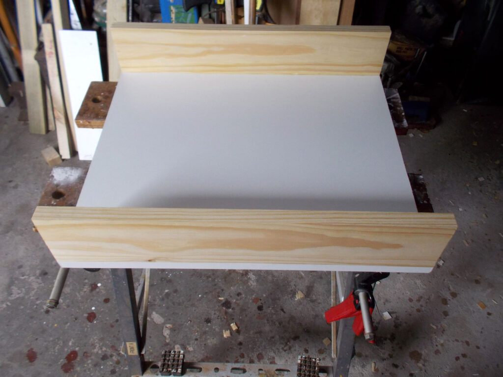
- Now for the sides… they were cut from 12x96mm SA pine but not secured along their length, but only to the front and rear pieces of the drawer. This is because they would be supported on the base which in turn is supported on the aluminium reinforcing support strip slider runner
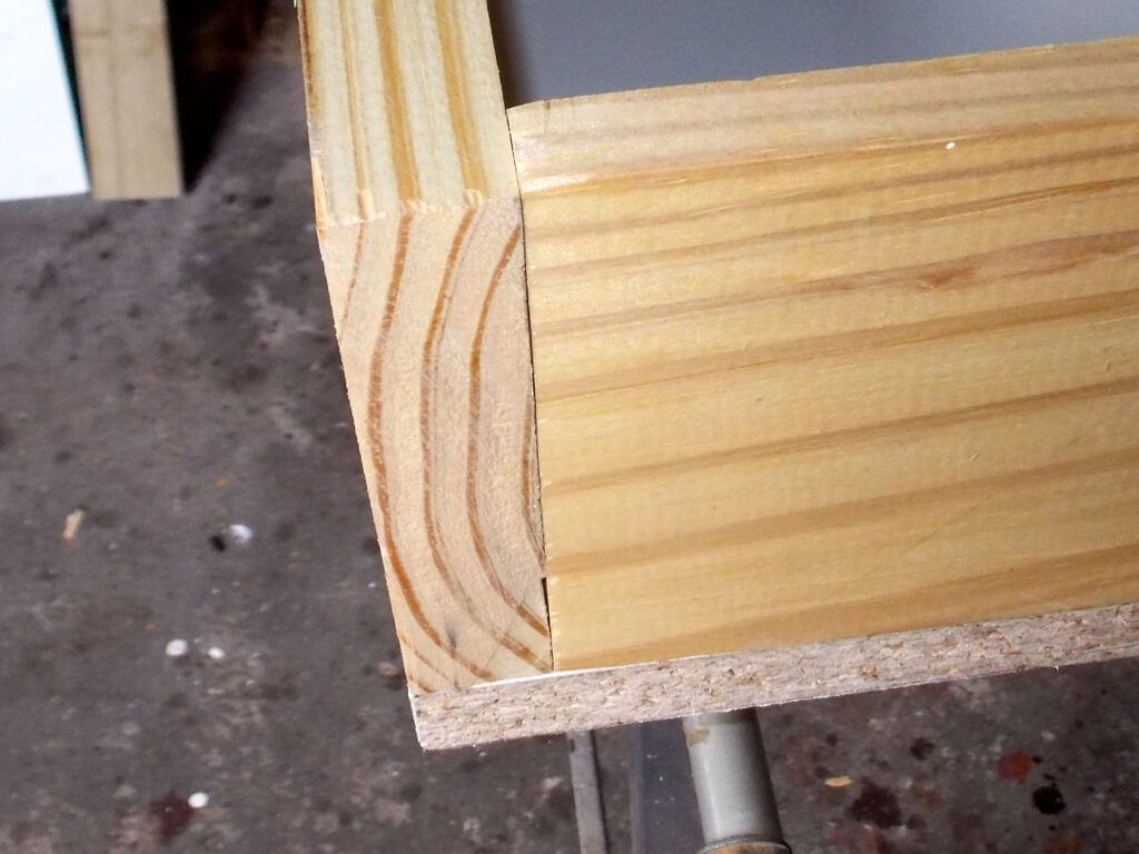
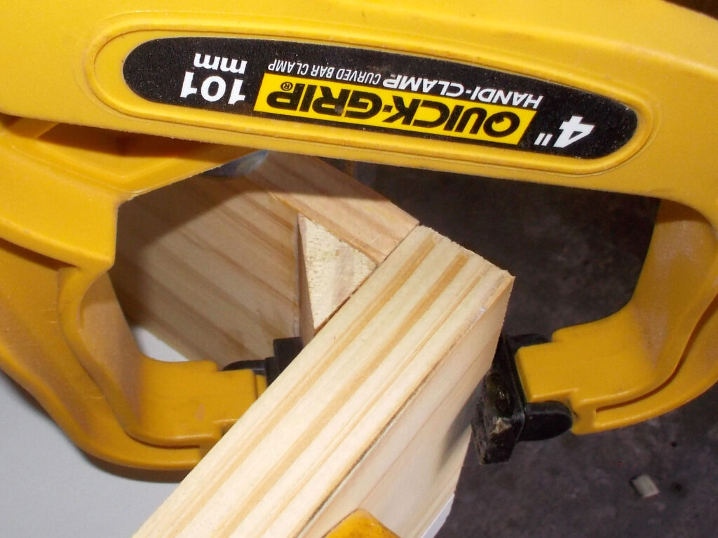
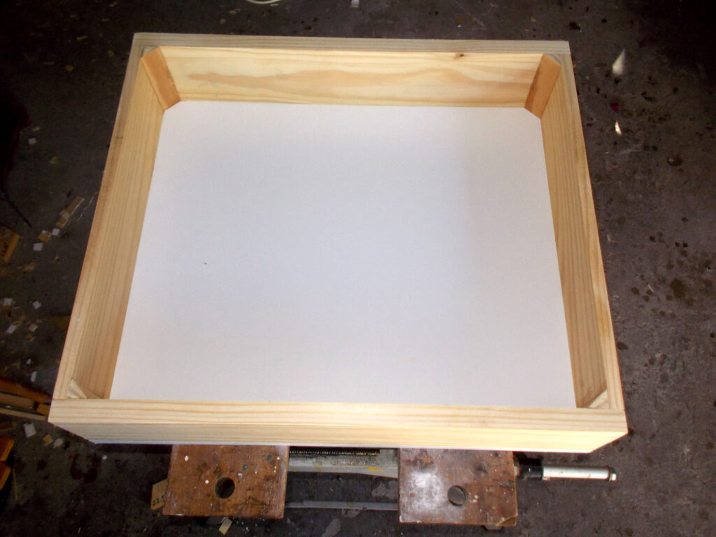
- They were secured with glue to the front and rear and the joins were reinforced with a length of 19mm 45° quadrant on each as additional reinforcement.
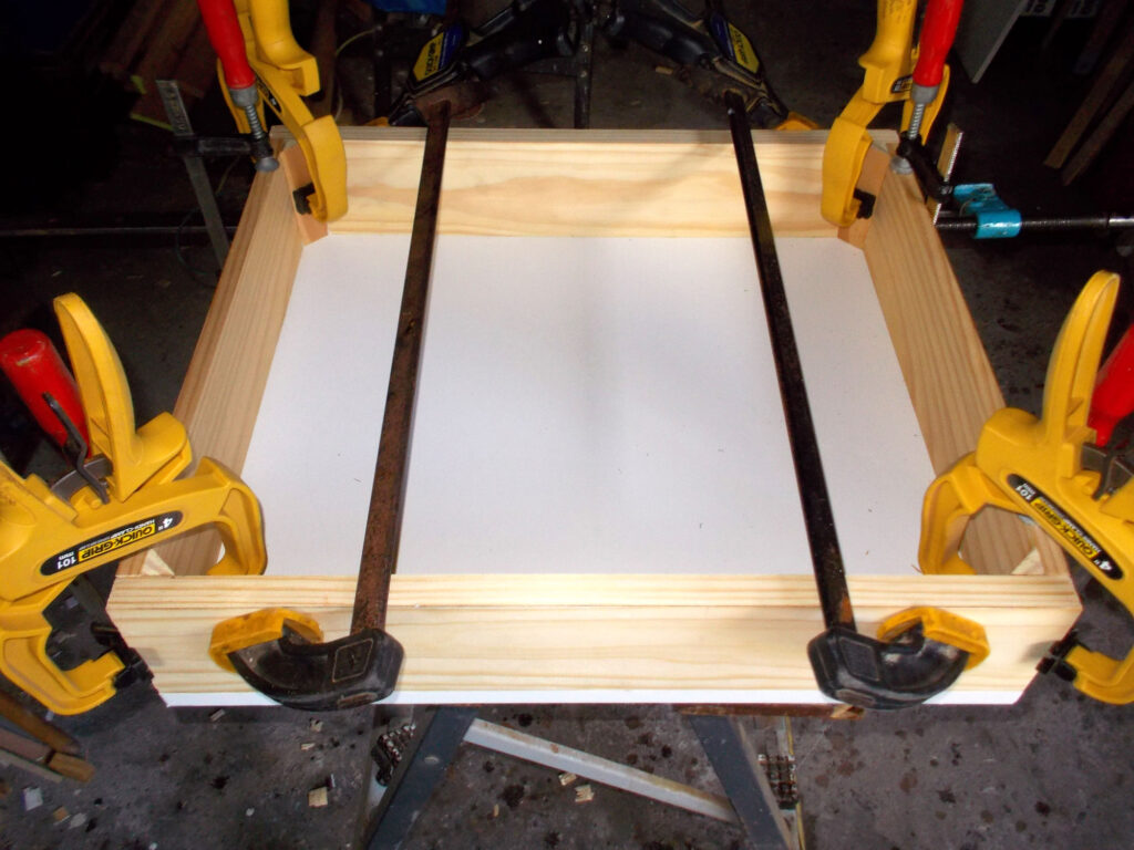
- Plenty of clamps ensured every join was fully fixed in position as the glue cured. Caution: when gluing joins, NEVER use clamping force to make good a bad join, and NEVER use excessive clamping force… all it will do is force too much glue out of the junctions between the glued surfaces and you will end up with a weaker bond.
- A close-up of one of the joins.
- The completed drawer… almost!
- To position the handle, I used a length of scrap wood to align it 22mm down from the top edge of the front… within reason the closer it is to the top edge of the front, of the drawer the higher it is from the floor and the easier it is for you to reach.
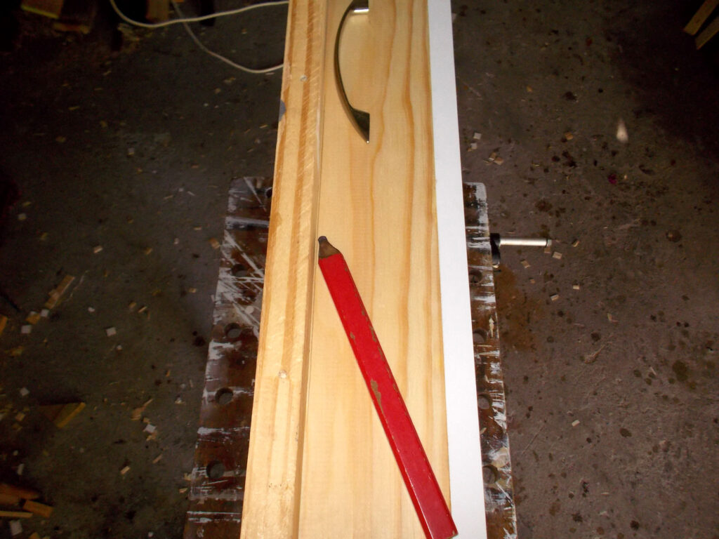
- I centred the handle on the drawer front and on the line and marked the positions of the attachment screw holes.

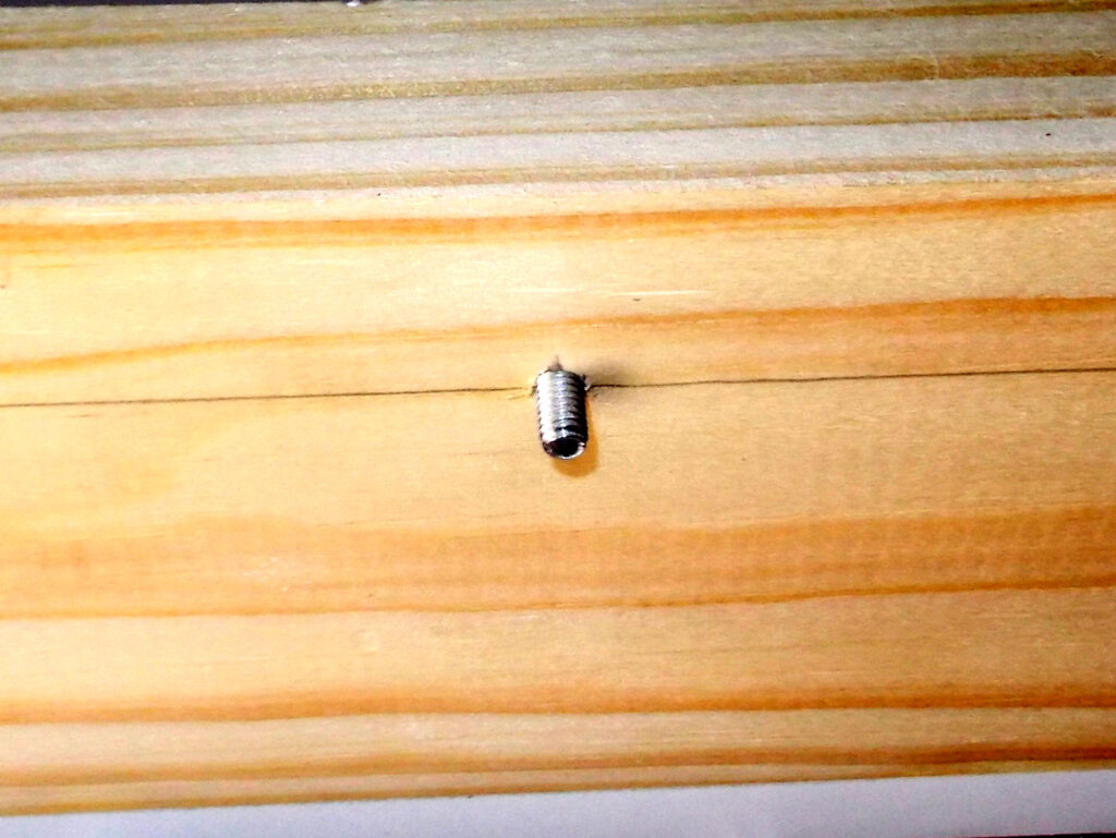
- Here the handle screw pan heads are flat on the surface of the inner surface of the front.
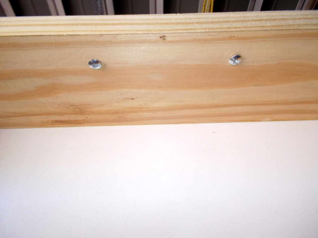
- They do not give much purchase on the handle, however. So…
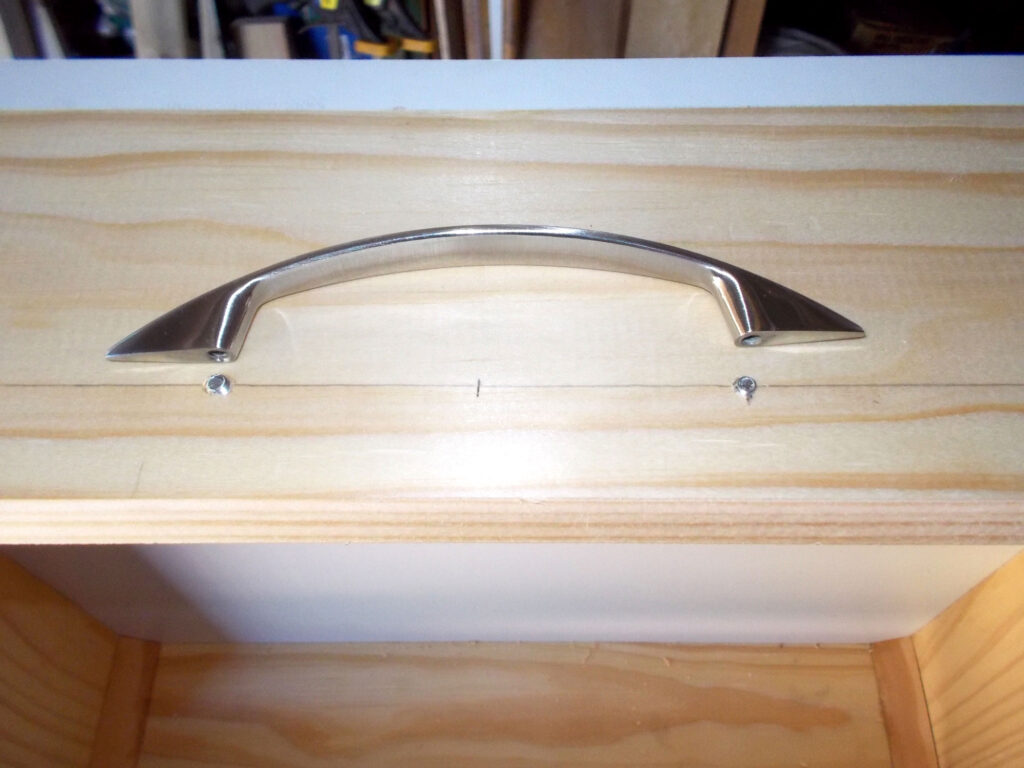
- I decided to countersink the heads about 4mm, using a countersink bit.
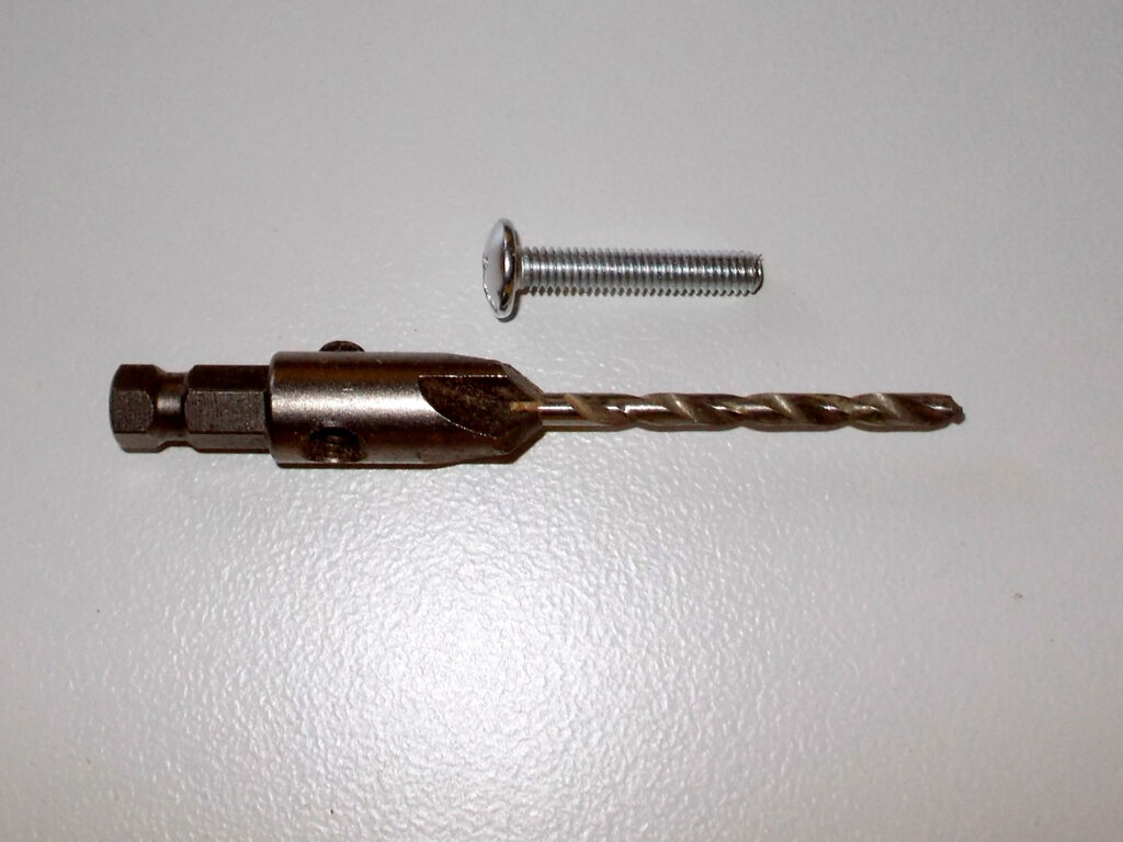
- I used tape to set my countersinking depth.

- Here are the heads countersunk to the required depth – and allowing more thread to be exposed on the outer surface and hence far better securing of the handle.
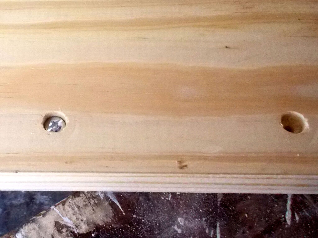
- As you can see… a big improvement.
- Before fitting the handle, however, first I secured the runners to the sides of the drawer, lining up the back end of the runner with the back edge of the drawer.
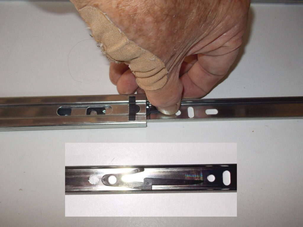
- In order to attach the runner to the drawer, it has to be separated from the main body. The way to do this is a follows: slider attachment to the tray sides themselves… the central sliding portion has to come out in order to be attached and to do this all you do is extend the slider fully and feel for the plastic locking lever. Flex it up and pull the slider’s central slider piece out. The inset shows the locking lever – there to ensure the tray is not pulled right out when in use.
- I used the same 6x41mm drywall screws to secure the runners to the drawer. However, first you need to use an HSS 4mmØ bit to make the holes in the aluminium reinforcing support at the required positions. I suggest do this first with just one position – the end one, to lock the runner in position. Then you can drill the rest of the holes. Note, ensure that you just drill through the aluminium, and not right into the chipboard base below.
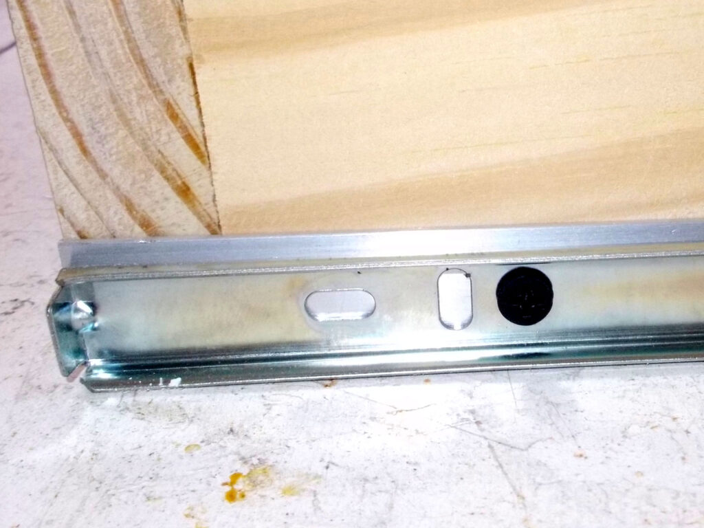
- This shows one of the securing screws. As when attaching the slider bodies to their mounting panels, as you drive in each screw, engage the slider main body and runner and ensure that there is full and free movement.
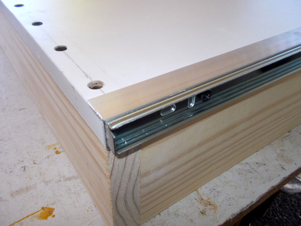
- Now for the slider mounting panel attachment screws… I decided on five per panel.
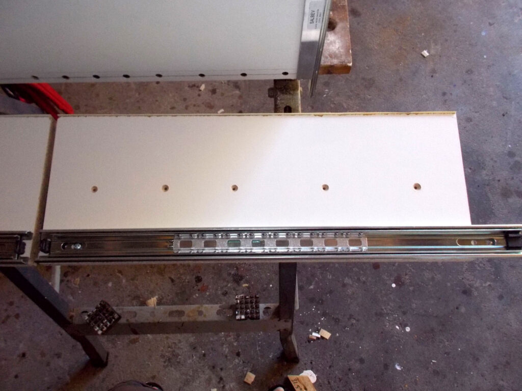
- Then I attached the slider mounting panels to the sides of the cupboard as shown, using five 6x30mm pan head screws per panel. This screw length ensures that the mounting panels are securely attached to the sides of the cabinet, but the tips of the screws do not protrude on the outside surface of the cabinet. The rear edge of each panel is hard up against the back of the cabinet backing panel.
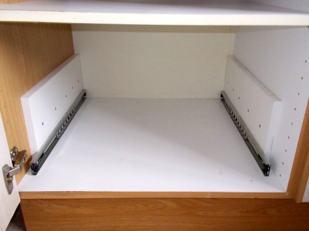
- Now to paint the drawer front. I used masking tape to blank off the aluminium reinforcing support strips and the drawer side panels and applied three coats of high gloss white enamel. Then once the final coat of paint had dried properly I attached the handle, securing it firmly.
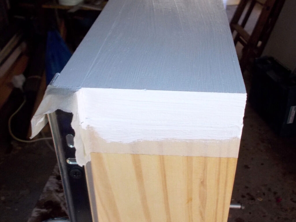
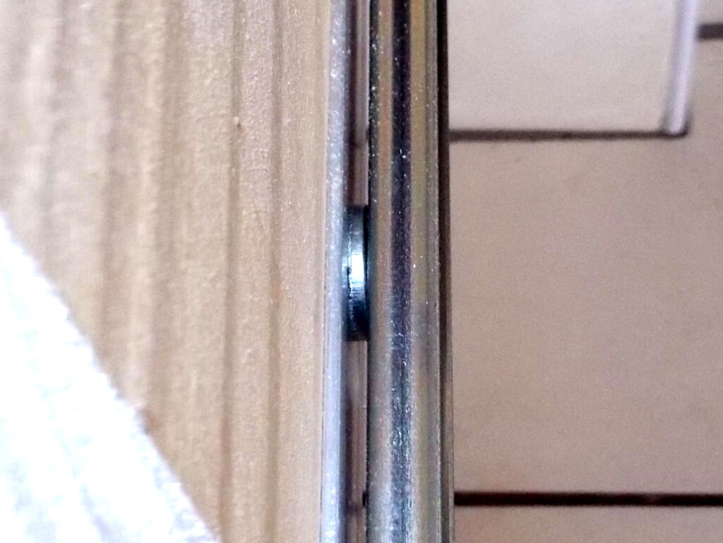
- A hint, if you find after all this that there is a little too much lateral (side-to-side) ‘play’ in the sliders, you can simply remove one or both runners and insert a washer at each screw attachment point, as shown here.
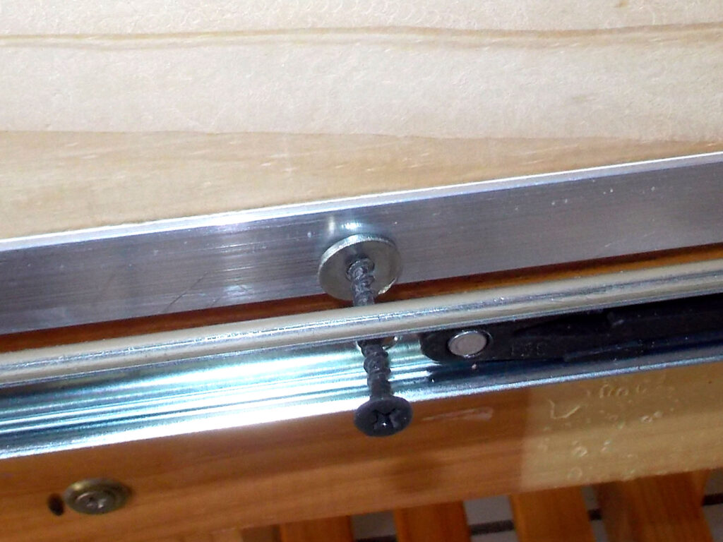
- This would effectively ‘widen’ the drawer and reduce the ‘play’.
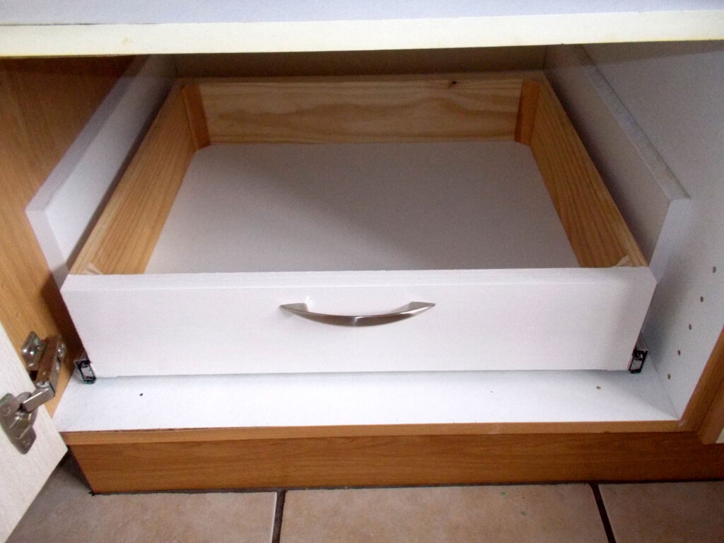
- Here is the empty drawer hiding coyly in the cabinet.
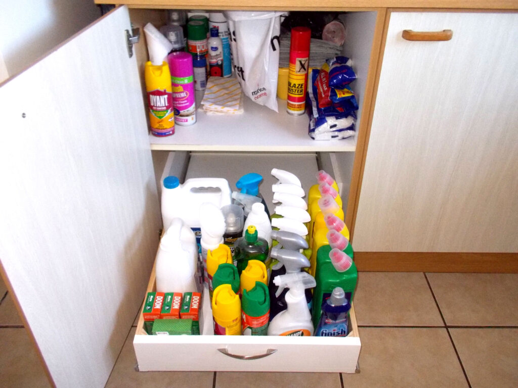
- As you can see it slides right out of the cabinet and now everything on it is now within easy reach without any grovelling.

- Tucked away out of the way…

- Now, what did I want again…? Ah! The surface cleaner, right at the back – but now very easy to reach.
Panel:
These materials are available at Selected Mica Stores. To find your closest Mica and whether or not they stock the items required, please go to www.mica.co.za, find your store and call them. If your local Mica does not stock exactly what you need they will be able to order it for you or suggest an alternative product or a reputable source.
Project guide
TIME: 1-2 working days
COST: R350-R600 (depending on the number of drawers you will be installing
Skill: 3 (all the cuts are at 90° but it is vital that the width of the drawer/s be absolutely precise – to the millimetre – so that it/they move freely on the sliders without any binding)
Tools required:
Circular cut-off saw, hacksaw, cordless drill/driver, sander and household clothes iron (if using iron-on chipboard edging tape).