03 February 2022

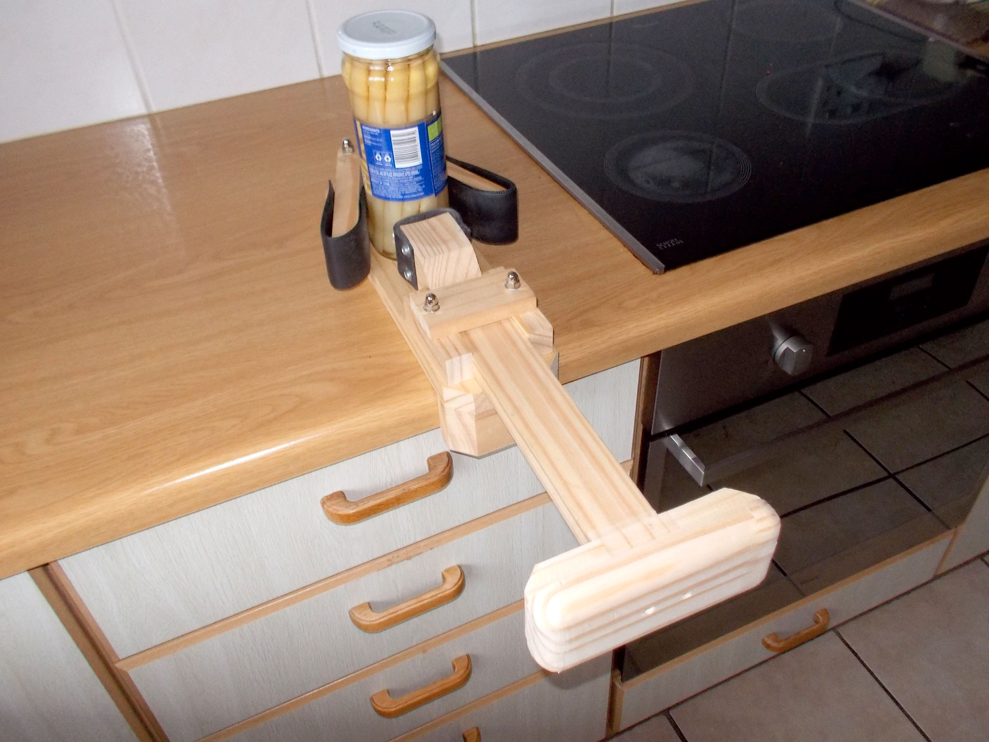
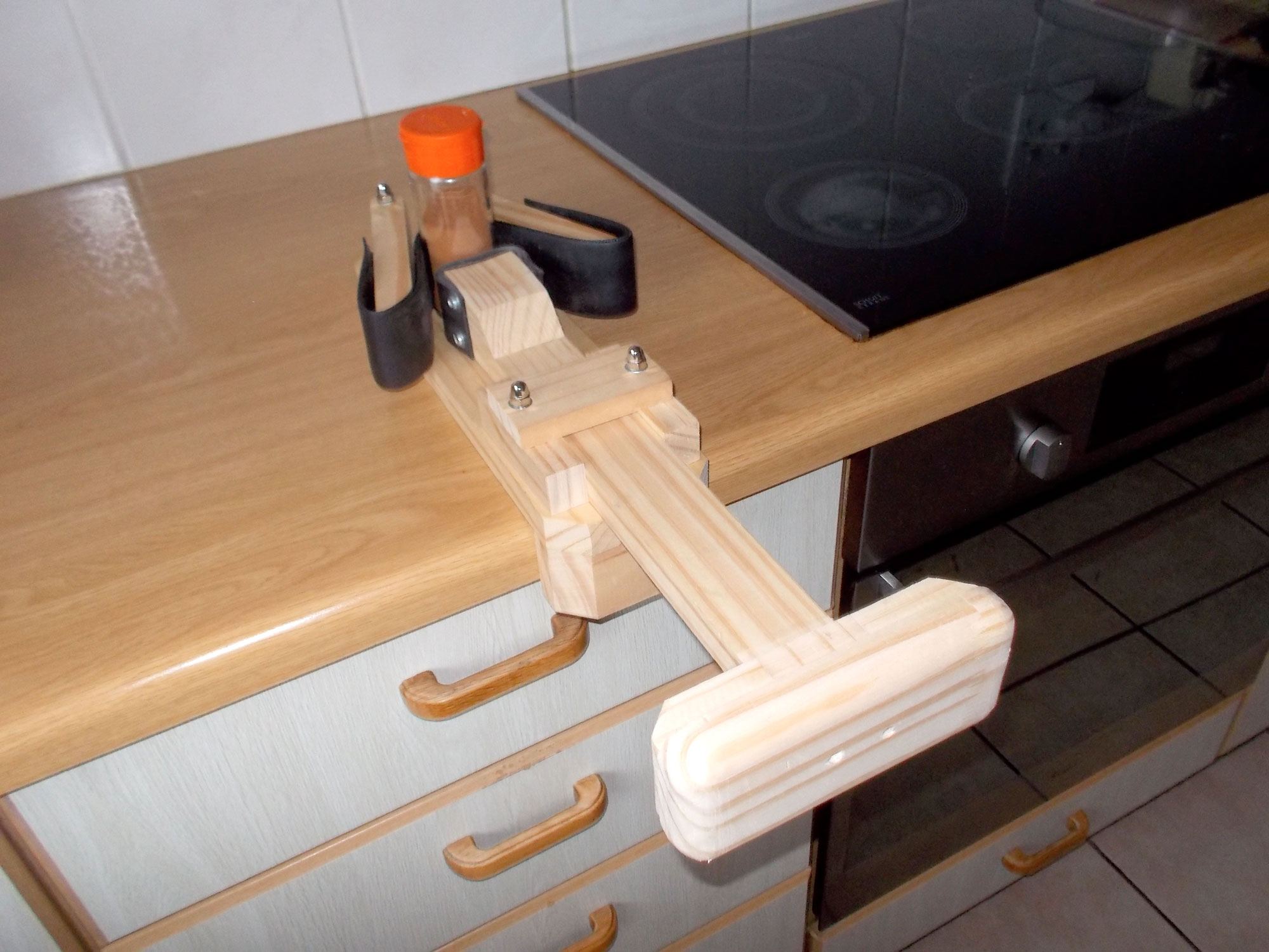
Your very own kitchen helping hand
When you are faced with having to hold a container with one hand while you use your other hand to try to remove a screw-top lid, and it’s just not working because you cannot bring enough torque to the effort, this handy third hand is your helping hand to the rescue.
As said, it’s no beauty, but this device does have one saving beauty spot… thanks to its design, it self-adjusts itself to whatever diameter of container you need to open that you are likely to find in your kitchen (subject of course to the diameter being so large that the container won’t even fit into the device, or so small that it cannot be gripped at all.
This is not something you will use every day, but it is one of those kitchen (or workshop) helpers that when you need it, it will do the job.
In passing, the whole unit is quite long when fully extended (560mm) and even when fully closed it is still 460mm long. This is because when you are opening of closing a container you usually do so a little way from your body. This unit helps you do that – particularly when you are using a strap opener on the lid.
Materials:
All these materials, apart from the washers, 6mm gutter bolts, dome nuts, nylon strap and door weather-proofing rubber strip are SA pine offcuts from earlier projects, so the cost is minimal. Hence the materials are as follows:
- SA pine (all leftovers from earlier projects):
- Main body – 22x96x330mm
- Swinging arms (2) – 22x44x160mm
- Plunger arm (1) – 22x44x350mm
- Plunger arm guides (2) – 22x24x90mm
- Plunger arm guide top bracket (1) – 12x44x85mm
- Plunger arm end-piece (1) – 22x44x50/70mm (end bevelled at 45°)
- Counter hook (1) – 32x44x96mm
- Plunger arm pad (1) – 22x69x150mm
- Plunger arm pad bracing (2) – 22x44x40/52mm (ends bevelled at 45°)
- Gutter bolts (4) – 6mmØx75mm (these might have to be trimmed a little depending on how deeply you countersink the heads in the main body – see the bullet-pointed hints relating to cutting bolts below)
- Washers:
- Washers (8) – 6mmØ
- Fender washers (2) – 6mmØx32mmØ
- Washers (12) – 4mmØ x 12mmØ
- Chromed dome nuts (4) – 6mmØ
- Nylon strap (1) – 50mm wide x 400mm long
- Rubber door weather strip – 50mm wide x 500mm long
- Screws:
- Pan head screws (12) – 16mm 4 gauge
- Wood screws (20) – 40mm 4 gauge
- Wood glue
- Finish of your choice – I left this natural
Method:
- The basic materials – note the SA pine offcuts. It’s always a good idea to keep reasonably sized offcuts from your projects… you never know when they might come inhandy.

- The nylon strap and the rubber weather strip. The reason for using the nylon strap is to enable you to exert clamping force on the container without the rubber strip simply stretching… and stretching…and stretching. It is actually the same principle used in car, bicycle, truck and all other tyres; all tyres have cords built into them to stop them simply ballooning ever larger when you inflate them. That is why tyres become harder – but not larger – when you inflate them.

- I started with the plunger arm. I cut the arm end-piece and glued it to the one end of the plunger.

- Then I used two 40mm screws to reinforce the join. The reason for the end-piece is to spread the pressure over the whole width of the strip – which is 50mm wide. Note that the screw heads are countersunk below the surface of the arm, so that they will not snag on the body as the plunger arm slides.

- I cut a 130mm length of the strip and two shorter lengths for extra cushioning and positioned them on the end of the plunger arm.

- Then I secured the strips with two 16mm pan head screws and 12mmØ washers as shown.

- The completed attachment.

- For a slightly neater finish on what is not the most beautiful project, I trimmed off excess strip.

- Then I sanded it down level with the top of the plunger arm end-piece.

- I bevelled the corners of the body at 45°.

- I also bevelled the ends of the swinging arms. On the left is the leading end, and on the right is the end to which the securing bolt will be fitted.

- I used a gauge to mark the centre of the ends of the arms, and a 6mmØ brad bit to make the holes.

- Here are two ends drilled… you need to be very precise, ensuring that the holes are absolutely vertical – otherwise the arms will not swing properly. They must be parallel with and flush against the body surface through their entire arcs as they swing.

- I clamped the arms to the end of the body and 22mm apart and used them as the guides to drill through the body. The pivot bolts are 30mm from the end of the body. This ensures that there is sufficient timber to take the strain as the user uses their body weight to clamp the container firmly in position.

- The bolt heads must be countersunk so that they do not scratch or mar the countertop surface, and I used a 16mmØ spade bit for this task. Job done.

Hint: The easiest way to confirm that the bolt head is below the body’s surface is to pass a credit card, spatula or any other implement with a straight edge over the head when it is fully seated. If you hear a ‘click’ or ‘clack’ you need to countersink the bolt head a little more. I used dome nuts to secure the bolts as they look better than simple hex or square nuts suppled with gutter bolts. I used the same procedure to secure the 12x44x85mm plunger arm guide top bracket to the guides – using two gutter bolts and dome nuts to secure it in position.
- I used contact adhesive to ensure the dome nuts would not loosen.

Hint: You can buy excellent nut locking products from Mica stores, but if you don’t have any handy, contact adhesive makes a good substitute. In this case I put a drop into each dome nut (a little overdone here, so I used a toothpick to remove the excess and used that on the second dome nut). When the nut is tightened, the contact adhesive is forced into the thread and when dry, locks the nut in place – though it can be removed if necessary. - The arms in position. Not the use of the two 6mmØx32mmØ fender washers to provide a bearing surface between the arms and the body. Note also that there is washer under the dome nut and another at the bolt head. These ensure that the bolts do not snag on the wood and over time loosen the dome nuts as the arms are swung in and out to suit the container being opened (or closed, for that matter).
Hints: if you need to trim a bolt to a particular length, here are three hints for you:
- Turn a nut onto the bolt a few turns beyond your cutting point. When the cut is made, turning the nut off the bolt will align and clean up the cut threads.

- Clamp the offcut end of the bolt in your vice – after all, if its threads are ruined, you weren’t going be using that end anyway, right?

- If you do plan to use both the bolt and the piece you cut off, cushion the bolt between two pieces of scrap wood to keep it firmly in place while you make the cut; this will ensure that the threads are not damaged. (And if you are using the offcut as well as the bolt itself, don’t forget to apply the nut hint to both sides of the cut you are making.)

- Now for the plunger arm guides. These were cut from a length of 22x44mm, but with a cross-section and length of 22x24x90mm respectively. This allows a little vertical movement of the plunger arm to make it a little more accommodating of the container mounted in the device. There should be a gap of about 1-1.5mm left-and-right so that the plunger arm can be moved with ease.

- With the guide clamped in position, they were each secured with two 40mm screws and glue.

- I used three 40mm screws to secure the 32x44x96mm counter hook. These screws will be hidden by the plunger arm.

- Now for the plunger arm pad. At this will be the part of the device being shoved by your body, it needs to be comfortable, so the ends were rounded off – I used a larger 40mmØ fender washer as my cutting guide.

- Remember what I said about offcuts? I was going to make a rather fancy assembly for the plunger arm to spread the bearing load on the container, but discarded it – but I saved the pieces.

- And as it turns out, quite serendipitously, they are a perfect fit as bracing for the plunger arm on the pad. (It is important that the pad is very securely attached to the end of the plunger arm… if it can loose under pressure the end of the plunger arm could be driven into the user’s flesh and be rather painful. Equally important is that the pad be positioned dead centre, on the centreline of the arm so that the user’s body weight is spread equally and evenly over the pad’s whole area.)

- The bracing pieces were glued to the pad and positioned so that they gripped the plunger arm very snugly, and secured with a screw each.

- They then acted as useful clamping points to hold the pad securely on the workbench.
Then I routed the entire edges of the pad. This is the final result.
- With the pad secured to the plunger arm using glue and two 40mm screws countersunk through the pad and into the arm, I added a little extra bracing from a couple of offcuts and sanded the whole unit down for a smooth finish.

- Now for the strap and strip for the swinging arms. The nylon strap is 50mm shorter than the weather strip.

- Hint: when you cut nylon strap, it is a good idea to melt the cut ends using a small blowtorch as shown here, or a lighter. This melts the threads and stops them unravelling.

- I marked off the position I wanted for the strap attachment and secured each end with two 16mm pan head screws and 12mmØ washers.

- Then is used a clamp to put the strap under tension and fitted the weather strip.

- Here’s the completed job – it doesn’t matter that the strip is a bit looser than the strap.

- Here is the attachment of the two – note how the end of the strip overlaps the end of the strap by about 25mm. this means that the 16mm securing screws are passing only through one layer before entering the wood arm. This makes for a slightly more secure join. You might have to move the ends of the strap and strip further out towards the end of the arm, or in towards the bolt end. That’s not a problem.

- The rubber strip needs to be dry and free of any debris if it is to grip the container properly. However…

- Hint: the strip grabs containers very effectively, but if you want a little more ‘grab’, a few rubber bands on the lid and container itself, will enhance the friction between the container and helping hand, and the lid and whatever you are using to loosen – or tighten it.
The helping hand in operation…
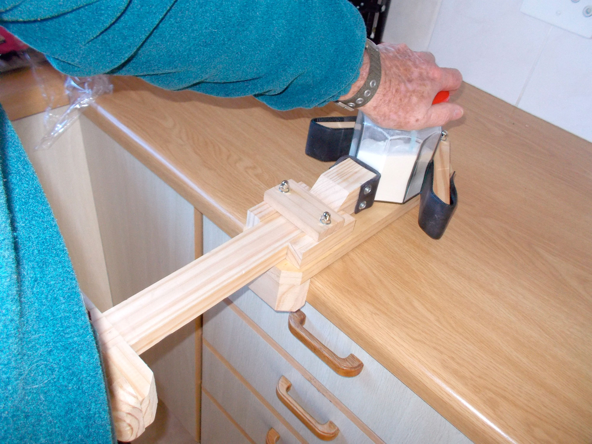
As you can see the unit handles containers of various diameters (even an octagonal one) and joy of joys… it holds a wine bottle securely as you remove the cork.
Project guide
Skill level: 2
Estimated time: 6-8 hours
Cost: R25-R50
Assistant: No
Tools required:
Drill/driver, jigsaw or circular cut-off saw, sander, router.
Panel:
These materials are available at Selected Mica Stores. To find your closest Mica and whether or not they stock the items required, please go to www.mica.co.za, find your store and call them. If your local Mica does not stock exactly what you need they will be able to order it for you or suggest an alternative product or a reputable source.